Download
1 / 4
40 likes | 199 Views
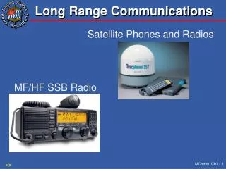
ARGOS receiver 1GHz … 2GHz → 0.1MHz…1GHz. Components panel. Front panel. Back panel and connectors. Overview Digital FFT Radio-Spektrograf. 1. IF-filter 8,500GHz B3dB=+-500MHz=1GHz -1dB. IF-isolator -0,7dB. 2. IF amplifier 0.1MHz...1GHz. RF-amplifier / equalizer. 1. mixer.

E N D
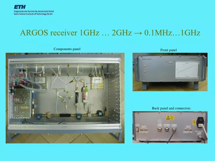
ARGOS receiver 1GHz … 2GHz → 0.1MHz…1GHz Components panel Front panel Back panel and connectors
Overview Digital FFT Radio-Spektrograf 1. IF-filter 8,500GHz B3dB=+-500MHz=1GHz -1dB IF-isolator -0,7dB 2. IF amplifier 0.1MHz...1GHz RF-amplifier / equalizer 1. mixer 2. mixer 1. IF-amplfier 8-12,4GHz -6dB -6dB N/SMA att -3dB Frf 26dB min NF<5dB RF IF IF RF 15dB BPF 41dB IF1 att -3dB LO LO +15V +15V +6dBm+-3dBm 10MHz Ref. Input +15V Synthesizer- isolator LO-isolator IF-isolator -0,7dB Video out N/SMA SMA- bridge Power Divider -6dB IF2 Aircable from antenna-tower to receiver -10dB @ 1,415GHz SMA- bridge Log. Detector +15V +15V Fsy Flo +5.0V Localoscillator #1 10,000GHz 13dBm min Localoscillator #2 9,000GHz 13dBm min Lowpassfilter F3dB=1GHz a=-1dB Power Divider -6dB Level: 104dB IF2=IF1-Flo IF1=Fsy-Frf Frf=Fsy-IF2-Flo IF2=Fsy-Flo-Frf ADC 8bit 2Gs/sec PC & FFT RX3 N/SMA DSP Astronomical Institute ETHZ Created by : Chr. Monstein , 13.12.1999 Updated by: Chr. Monstein, 21.05.2004 File: RX1GHz.ppt Revision: 1.5
Frequency diagram 1. Localoscillator LO1 = 10,000 GHz Upper sideband USB will not be used Power Selection of lower sideband LSB by bandpassfilter 1. mixer stage F1 = LO1 ± Frf = 8,500 GHz ± 500 MHz Frequency Fh=2,0 GHz Frf =1,5 GHz Fl=1,0 GHz F1h=9,00GHz F1z=8,50GHz F1l=8,00GHz Power 2. mixer stage 2. Localoscillator LO2 = 9,000 GHz Selection with lowpassfilter F2 = F1 - LO2 = 500 MHz ± 500 MHz Frequency F2h = 1000 MHz F2l = 0.1 MHz
ARGOS receiver as a frontend to CALLISTO radio-spectrometer Input freqeuncy ARGOS baseband 0.1MHz…1GHz received by CALLISTO which accepts 45MHz…870MHz