Download
1 / 78
780 likes | 897 Views
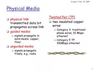
physical link: transmitted data bit propagates across link guided media: signals propagate in solid media: copper, fiber unguided media: signals propagate freely, e.g., radio. Twisted Pair (TP) two insulated copper wires Category 3: traditional phone wires, 10 Mbps ethernet

E N D
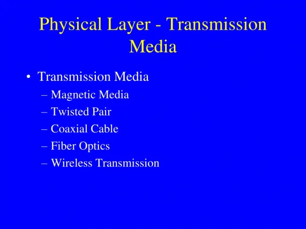
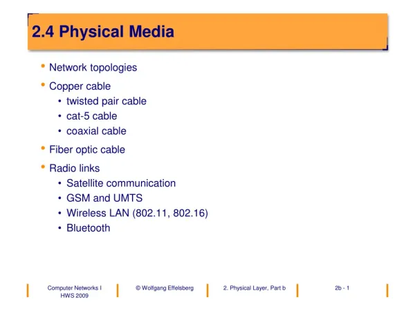
physical link: transmitted data bit propagates across link guided media: signals propagate in solid media: copper, fiber unguided media: signals propagate freely, e.g., radio Twisted Pair (TP) two insulated copper wires Category 3: traditional phone wires, 10 Mbps ethernet Category 5 TP: 100Mbps ethernet Physical Media
Coaxial cable: wire (signal carrier) within a wire (shield) baseband: single channel on cable broadband: multiple channel on cable bidirectional common use in 10Mbs Ethernet Physical Media: coax, fiber Fiber optic cable: • glass fiber carrying light pulses • high-speed operation: • 100Mbps Ethernet • high-speed point-to-point transmission (e.g., 5 Gps) • very low error rate
signal carried in electromagnetic spectrum no physical “wire” bidirectional propagation environment effects: reflection obstruction by objects interference Physical media: radio Radio link types: • microwave • e.g. up to 45 Mbps channels • LAN (e.g., waveLAN) • 2Mbps, 11Mbps • wide-area (e.g., cellular) • e.g. CDPD, 10’s Kbps • satellite • up to 50Mbps channel (or multiple smaller channels) • 270 Msec end-end delay • geosynchronous versus LEOS (low earth orbit)
Our goals: understand principles behind data link layer services: error detection, correction sharing a broadcast channel: multiple access link layer addressing instantiation and implementation of various link layer technologies Overview: link layer services error detection, correction multiple access protocols and LANs link layer addressing specific link layer technologies: Ethernet The Data Link Layer
M H H H H H H H H H t n l t t n l t n M M application transport network link physical M Link Layer: setting the context • two physically connected devices: • host-router, router-router, host-host • unit of data: frame network link physical data link protocol M frame phys. link adapter card
Link Layer Services • Framing, link access: • encapsulate datagram into frame, adding header, trailer • implement channel access if shared medium, • ‘physical addresses’ used in frame headers to identify source, destination • different from IP address! • Reliable delivery between two physically connected devices: • seldom used on low bit error link (fiber, some twisted pair) • wireless links: high error rates
Link Layer Services (more) • Flow Control: • pacing between sender and receivers • Error Detection: • errors caused by signal attenuation, noise. • receiver detects presence of errors: • signals sender for retransmission or drops frame • Error Correction: • receiver identifies and corrects bit error(s) without resorting to retransmission
M H H H H H H H H H t n l t t n l t n M M application transport network link physical M Link Layer: Implementation • implemented in “adapter” • e.g., PCMCIA card, Ethernet card • typically includes: RAM, DSP chips, host bus interface, and link interface network link physical data link protocol M frame phys. link adapter card
Error Detection • EDC= Error Detection and Correction bits (redundancy) • D = Data protected by error checking, may include header fields • Error detection not 100% reliable! Q: why? • protocol may miss some errors, but rarely • larger EDC field yields better detection and correction
Two Dimensional Bit Parity: Detect and correct single bit errors Single Bit Parity: Detect single bit errors 0 0 Parity Checking
Sender: treat segment contents as sequence of 16-bit integers checksum: addition (1’s complement sum) of segment contents sender puts checksum value into UDP checksum field Receiver: compute checksum of received segment check if computed checksum equals checksum field value: NO - error detected YES - no error detected. But maybe errors nonetheless? Internet checksum Goal: detect “errors” (e.g., flipped bits) in transmitted segment (note: used at transport layer only)
Checksumming: Cyclic Redundancy Check • view data bits, D, as a binary number • choose r+1 bit pattern (generator), G • goal: choose r CRC bits, R, such that • <D,R> exactly divisible by G (modulo 2) • receiver knows G, divides <D,R> by G. If non-zero remainder: error detected! • can detect all burst errors less than r+1 bits • widely used in practice (ATM, HDCL)
CRC Example Want: D.2r XOR R = nG equivalently: D.2r = nG XOR R equivalently: if we divide D.2r by G, want reminder R D.2r G R = remainder[ ]
Multiple Access Links and Protocols Three types of “links”: • point-to-point (single wire, e.g. PPP, SLIP) • broadcast (shared wire or medium; e.g, Ethernet, Wavelan, etc.) • switched (e.g., switched Ethernet, ATM etc)
Multiple Access protocols • single shared communication channel • two or more simultaneous transmissions by nodes: interference • only one node can send successfully at a time • multiple access protocol: • distributed algorithm that determines how stations share channel, i.e., determine when station can transmit • communication about channel sharing must use channel itself! • what to look for in multiple access protocols: • synchronous or asynchronous • information needed about other stations • robustness (e.g., to channel errors) • performance
MAC Protocols: a taxonomy Three broad classes: • Channel Partitioning • divide channel into smaller “pieces” (time slots, frequency) • allocate piece to node for exclusive use • Random Access • allow collisions • “recover” from collisions • “Taking turns” • tightly coordinate shared access to avoid collisions Goal: efficient, fair, simple, decentralized
MAC Protocols: Goal • Channel Rate = R bps • Efficient: • Single user:Throughput R • Fairness • N users • Min. user throughput R/N • Decentralized • Fault tolerance • Simple
The parameter ‘a’ • The number of packets sent by a source before the farthest station receives the first bit
Base technologies • Isolates data from different sources • Three basic choices • Frequency division multiple access (FDMA) • Time division multiple access (TDMA) • Code division multiple access (CDMA)
FDMA • Simplest • Best suited for analog links • Each station has its own frequency band, separated by guard bands • Receivers tune to the right frequency • Number of frequencies is limited • reduce transmitter power; reuse frequencies in non-adjacent cells • example: voice channel = 30 KHz • 833 channels in 25 MHz band
TDMA • All stations transmit data on same frequency, but at different times • Needs time synchronization • Pros • users can be given different amounts of bandwidth • mobiles can use idle times to determine best base station • can switch off power when not transmitting • Cons • synchronization overhead
CDMA • Users separated both by time and frequency • Send at a different frequency at each time slot (frequency hopping) • Or, convert a single bit to a code (direct sequence) • receiver can decipher bit by inverse process • Pros • hard to spy • immune from narrowband noise • no need for all stations to synchronize • no hard limit on capacity of a cell • all cells can use all frequencies
CDMA • Cons • implementation complexity • need for a large contiguous frequency band (for direct sequence)
FDD and TDD • Two ways of converting a wireless medium to a duplex channel • In Frequency Division Duplex, uplink and downlink use different frequencies • In Time Division Duplex, uplink and downlink use different time slots
Outline • Contexts for the problem • Choices and constraints • Performance metrics • Base technologies • Centralized schemes • Distributed schemes
Channel Partitioning MAC protocols: TDMA TDMA: time division multiple access • access to channel in "rounds" • each station gets fixed length slot (length = pkt trans time) in each round • unused slots go idle • example: 6-station LAN, 1,3,4 have pkt, slots 2,5,6 idle • TDM (Time Division Multiplexing): channel divided into N time slots, one per user; inefficient with low duty cycle users and at light load. • FDM (Frequency Division Multiplexing): frequency subdivided.
Channel Partitioning MAC protocols: FDMA FDMA: frequency division multiple access • channel spectrum divided into frequency bands • each station assigned fixed frequency band • unused transmission time in frequency bands go idle • example: 6-station LAN, 1,3,4 have pkt, frequency bands 2,5,6 idle • TDM (Time Division Multiplexing): channel divided into N time slots, one per user; inefficient with low duty cycle users and at light load. • FDM (Frequency Division Multiplexing): frequency subdivided. time frequency bands
TDMA & FDMA: Performance • Channel Rate = R bps • Single user • Throughput R/N • Fairness • Each user gets the same allocation • Depends on maximum number of users • Decentralized • Requires division • Simple
Random Access protocols • When node has packet to send • transmit at full channel data rate R. • no a priori coordination among nodes • two or more transmitting nodes -> “collision”, • random access MAC protocol specifies: • how to detect collisions • how to recover from collisions (e.g., via delayed retransmissions) • Examples of random access MAC protocols: • slotted ALOHA • ALOHA • CSMA and CSMA/CD
Slotted Aloha • time is divided into equal size slots (= pkt trans. time) • node with new arriving pkt: transmit at beginning of next slot • if collision: retransmit pkt in future slots with probability p, until successful. Success (S), Collision (C), Empty (E) slots
At best: channel use for useful transmissions 37% of time! Slotted Aloha efficiency Q: what is max fraction slots successful? A: Suppose N stations have packets to send • each transmits in slot with probability p • prob. successful transmission S is: by single node: S= p (1-p)(N-1) by any of N nodes S = Prob (only one transmits) = N p (1-p)(N-1) … choosing optimum p as N -> infty ... = 1/e = .37 as N -> infty
Pure (unslotted) ALOHA • unslotted Aloha: simpler, no synchronization • pkt needs transmission: • send without awaiting for beginning of slot • collision probability increases: • pkt sent at t0 collide with other pkts sent in [t0-1, t0+1]
0.4 0.3 Slotted Aloha protocol constrains effective channel throughput! 0.2 0.1 Pure Aloha 1.5 2.0 0.5 1.0 G = offered load = Np Pure Aloha (cont.) P(success by given node) = P(node transmits) . P(no other node transmits in [t0-1,t0] . P(no other node transmits in [t0,t0+1] = p . (1-p)N-1 . (1-p)N-1 P(success by any of N nodes) = N p . (1-p)N-1 . (1-p)N-1 … choosing optimum p as N -> infty ... = 1/(2e) = .18 S = throughput = “goodput” (success rate)
Aloha: Performance • Channel Rate = R bps • Single user • Throughput R ! • Fairness • Multiple users • Combined throughput only 0.37*R • Decentralized • Slotted needs slot synchronization • Simple
CSMA: Carrier Sense Multiple Access) CSMA: listen before transmit: • If channel sensed idle: transmit entire pkt • If channel sensed busy, defer transmission • Persistent CSMA: retry immediately with probability p when channel becomes idle (may cause instability) • Non-persistent CSMA: retry after random interval • human analogy: don’t interrupt others!
CSMA collisions spatial layout of nodes along ethernet collisions can occur: propagation delay means two nodes may not yet hear each other’s transmission collision: entire packet transmission time wasted note: role of distance and propagation delay in determining collision prob.
CSMA/CD (Collision Detection) CSMA/CD: carrier sensing, deferral as in CSMA • collisions detected within short time • colliding transmissions aborted, reducing channel wastage • persistent or non-persistent retransmission • collision detection: • easy in wired LANs: measure signal strengths, compare transmitted, received signals • difficult in wireless LANs: receiver shut off while transmitting
CDMA/CD • Channel Rate = R bps • Single user • Throughput R • Fairness • Multiple users • Depends on Detection Time • Decentralized • Completely • Simple • Needs collision detection hardware
“Taking Turns” MAC protocols channel partitioning MAC protocols: • share channel efficiently at high load • inefficient at low load: delay in channel access, 1/N bandwidth allocated even if only 1 active node! Random access MAC protocols • efficient at low load: single node can fully utilize channel • high load: collision overhead “taking turns” protocols look for best of both worlds!
Token passing: • control token passed from one node to next sequentially. • token message • concerns: • token overhead • latency • single point of failure (token) “Taking Turns” MAC protocols Polling: • master node “invites” slave nodes to transmit in turn • Request to Send, Clear to Send msgs • concerns: • polling overhead • latency • single point of failure (master)
Summary of MAC protocols • What do you do with a shared media? • Channel Partitioning, by time, frequency or code • Time Division,Code Division, Frequency Division • Random partitioning (dynamic), • CSMA, CSMA/CD • carrier sensing: easy in some technologies (wire), hard in others (wireless) • CSMA/CD used in Ethernet • Taking Turns • polling from a central cite, token passing
Performance metrics • Normalized throughput • fraction of link capacity used to carry non-retransmitted packets • example • with no collisions, 1000 packets/sec • with a particular scheme and workload, 250 packets/sec • => goodput = 0.25 • Mean delay • amount of time a station has to wait before it successfully transmits a packet • depends on the load and the characteristics of the medium
Performance metrics • Stability • with heavy load, is all the time spent on resolving contentions? • => unstable • with a stable algorithm, throughput does not decrease with offered load • if infinite number of uncontrolled stations share a link, then instability is guaranteed • but if sources reduce load when overload is detected, can achieve stability • Fairness • no single definition • ‘no-starvation’: source eventually gets a chance to send
Centralized access schemes • One station is master, and the other are slaves • slave can transmit only when master allows • Natural fit in some situations • wireless LAN, where base station is the only station that can see everyone • cellular telephony, where base station is the only one capable of high transmit power
Centralized access schemes Circuit mode • When station wants to transmit, it sends a message to master using packet mode • Master allocates transmission resources to slave • Slave uses the resources until it is done • No contention during data transfer • Used primarily in cellular phone systems
Centralized access schemes Polling • Centralized packet-mode multiple access schemes • Polling • master asks each station in turn if it wants to send (roll-call polling) • inefficient if only a few stations are active, overhead for polling messages is high, or system has many terminals
Centralized access schemes Reservation-based schemes • When ‘a’ is large(mainly for satellite links), can’t use a distributed scheme for packet mode (too many collisions) • Instead master coordinates access to link using reservations • Some time slots devoted to reservation messages • can be smaller than data slots => minislots • Stations contend for a minislot (or own one) • Master decides winners and grants them access to link • Packet collisions are only for minislots, so overhead on contention is reduced