Download

1 / 18
180 likes | 374 Views
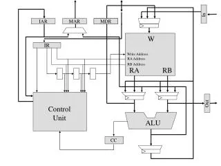
Internal processor. b. us. R. i. in. R. i. R. i. out. Y. in. Y. Constant 4. Select. MUX. A. B. ALU. Z. in. Z. Z. out. Figure 7.2. Input and output gating for the registers in Figure 7.1. Figure 7.3. Input and output gating for one register bit.

E N D
Internal processor b us R i in R i R i out Y in Y Constant 4 Select MUX A B ALU Z in Z Z out Figure 7.2. Input and output gating for the registers in Figure 7.1.
Figure 7.4. Connection and control signals for register MDR.
Step Action 1 PC , MAR , Read, Select4, Add, Z in in out 2 Z , PC , Y , WMF C out in in 3 MDR , IR out in 4 Offset-field-of-IR , Add, Z out in 5 Z , PC , End in out Figure 7.7. Control sequence for an unconditional branch instruction.
Step Action 1 PC , R=B, MAR , Read, IncPC out in 2 WMF C 3 MDR , R=B, IR in outB 4 R4 , R5 , SelectA, Add, R6 , End outA outB in Figure 7.9. Control sequence for the instruction. Add R4,R5,R6, for the three-bus organization in Figure 7.8.
CLK Control step Clock counter External inputs Decoder/ IR encoder Condition codes Control signals Figure 7.10. Control unit organization.
Branch Add T T 4 6 T 1 Figure 7.12. Generation of the Zincontrol signal for the processor in Figure 7.1.
Address Microinstruction 0 PC , MAR , Read, Select4, Add, Z in in out 1 Z , PC , Y , WMF C out in in 2 MDR , IR out in 3 Branch to starting address of appropriate microroutine . . . . . . . . . . . . . . . . . . . . . . . . . . . . . . . . . . . . . . . . . . . . . . . . . . . . . . . . . . . . . . . . . . 25 If N=0, then branch to microinstruction 0 26 Offset-field-of-IR , SelectY, Add, Z out in 27 Z , PC , End out in Figure 7.17. Microroutine for the instruction Branch<0.
External inputs Starting and Condition branch address IR codes generator Clock m P C Control CW store Figure 7.18. Organization of the control unit to allow conditional branching in the microprogram.