Download
1 / 22
230 likes | 373 Views
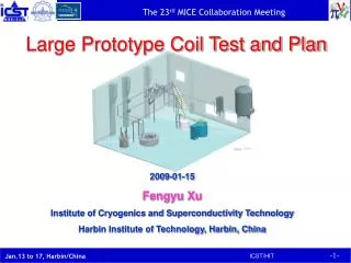
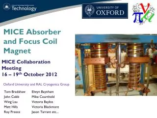
Allan DeMello Lawrence Berkeley National Laboratory. MICE Prototype Coupling Coil Fabrication Update. MICE CM38 - Napa California February 25, 2014. Outline. Cold mass Prototype vacuum vessel Prototype thermal shield Prototype cooling circuit. MICE Cooling Channel.

E N D
Allan DeMello Lawrence Berkeley National Laboratory MICE Prototype Coupling Coil Fabrication Update MICE CM38 - Napa California February 25, 2014
Outline • Cold mass • Prototype vacuum vessel • Prototype thermal shield • Prototype cooling circuit
MICE Cooling Channel Two coupling coil magnets integrated into the RFCC modules Focus magnets Spectrometer solenoid magnets
Superconductor Lead Stabilizers • Preparation cold mass coil #1 finished at LBNL January 2013 • Preparation of cold mass coils #2, #3 and #4 at LBNL to begin when coils arrive from China • Cernox Sensor • Voltage Taps • Strain Gauges • Quench Protection Prototype Coupling Coil Cold Mass
The 1st cold mass is currently undergoing magnetic testing at Fermilab Prototype Cold Mass Magnetic Test at Fermilab
LBNL mechanical shop is in the process of fabricating the first cryostat vacuum vessel • Estimated completion the end of March (vacuum vessel, tower, warm bore) • Drawings will be updated to reflect the “as built” cryostat Prototype Coupling Coil Vacuum Vessel
Coupling Coil Coupling coil magnet integrated into the RFCC RFCC Module
Tight tolerance for vacuum vessel scallops • Because of the tight clearance distance (2 mm) between the concave radius of the scallop and the O.D. of the RF coupler vacuum vessel spool a tight tolerance was placed on the final locations of the welded scallops. • The tolerance is true position within 0.254 mm Scallops Prototype Coupling Coil Scallop Clearance
Limited space between inner surface of the scallop and the thermal shield • MLI superinsulation must also fit inside the 12.5 mm gap between the thermal shield and the inner surface of the scallop. Prototype Coupling Coil Scallop Clearance
Tight tolerance on the final locations of the welded scallops. Prototype Coupling Coil Vacuum Vessel Tolerance
Original Scallop Design • Original thin walled scallop deformed during welding Gap shows the distortion from welding the scallop to the vacuum vessel Prototype Coupling Coil Scallop
New Scallop Design • New design has thicker walls at location of welds to help minimize the distortion Prototype Coupling Coil Scallop
Alignment Fixture for Welding Scallops • Scallop alignment fixture • LBNL shop developed a go/no go alignment fixture to ease the welding process for the scallops • Scallop alignment fixture • Nominal and ± indicators
Prototype Vacuum Vessel Welding Complete • Next steps for vacuum vessel • LBNL shop will machine the central bore and the tower flange • Finish machine the tower • Complete the warm bore roll-up • Vacuum check the vessel, the tower and the warm bore • Ports and bore shown covered due to the bead blasting process
Status • Initial thermal shield design and drawings were completed • Reviewed by LBNL Superconductor Magnet Group • Design is being revised for ease of fabrication and assembly (see following slides) Prototype Thermal Shield
Design concept from Fermilab shown • Thermal shield fabricated in two symmetric halves • Eliminates welding of TS as final assembly step • Removes the risk of damage to the MLI wrapped around the cold mass • New model and drawings will need to be generated New Concept For The Thermal Shield
Concept model of split thermal shield with edge lip for fasteners • Full assembly • Lips joined by fasteners • Half of assembly New Concept For The Thermal Shield
Prototype Cooling Circuit Assembly • Status • Initial design drawings have been finished and reviewed by the LBNL Superconducting Magnet group • Revisions required before requesting quotes from outside vendors • Also requires addition of fiducial target mount points • LBNL will ship cooling circuit as two sub-assemblies, to be integrated at FNAL in final assembly
Cold Mass / Thermal Shield Mock-up • A wood mock-up of the cold mass/thermal shield is being planned to assist in defining the coupling coil magnet assembly procedure
Projected Schedule • Cryostat vacuum vessel components • Completed end of March, shipped to FNAL in April • Incorporation of red-lines into final drawings by ~mid-June • Thermal shield • Redesign & drawings to be completed by end of March • Fabrication estimated complete by end of May • Cooling circuit • Drawing revisions to be completed by mid-April • Fabrication estimated complete by July/August • Cold mass mockup • Design complete by end of February • Fabrication complete by end of March
Summary of Prototype Coupling Coil • Cold Mass • LBNL finished cold mass preparation work January 2013 • Cold mass is currently being tested at Fermilab • Cryostat Vacuum Vessel • LBNL mechanical shop is fabricating the first cryostat vacuum vessel • Scheduled to finish the end of March • Thermal Shield • Initial design drawings have been finished and have been reviewed by the LBNL superconducting magnet group • New thermal shield concept introduced by Fermilab • New model and drawings need to be generated prior to fabrication • Cooling Circuit • Initial design drawings have been reviewed by the LBNL superconducting magnet group • Revisions required before requesting fabrication quotes • LBNL will integrate components into two sub-assemblies to be shipped to FNAL this summer