Download
1 / 78
800 likes | 1.05k Views
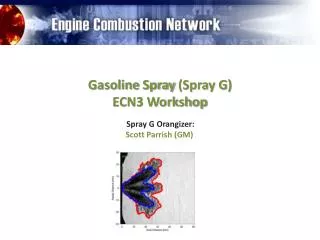
Spray G Modeling. ECN 3.0 April 5 th , 2014. Modeling Outline. Case description Modeling approaches CFD Measurement definitions Modeling results Liquid and vapor penetration Spray visualization Mixture fraction and drop size (SMD) profiles Summary.

E N D
Spray G Modeling ECN 3.0 April 5th, 2014
Modeling Outline • Case description • Modeling approaches • CFD Measurement definitions • Modeling results • Liquid and vapor penetration • Spray visualization • Mixture fraction and drop size (SMD) profiles • Summary
CFD Penetration Measurement Details • Liquid Penetration • 0.1 % Liquid volume fraction threshold • Vapor Penetration • 0.1 % Mixture fraction threshold • Measured along injector axis • Zero point at injector tip Penetration Length Side View
Mixture Fraction and SMD Profile Locations • Spray Axis • Along centerline of a spray jet • Injector Axis • Along the injector axis • Radial • Radially through spray jet center point in a plane 15 mm downstream • Transverse • Perpendicular to radial profile through spray jet center point in a plane 15 mm downstream • Dual-plume • On a line connecting the center points of two neighboring spray jets in a plane 15 mm downstream
Profile Location – Spray Axis • Along the centerline of an individual spray jet • Distanced measure along the spray axis • Zero at injection location, positive towards spray tip Profile Line Profile Line Top View Side View
Profile Location – Injector Axis • Along the injector axis • Distance measure along the injector axis • Zero at nozzle tip, positive towards leading edge Profile Line Top View Side View
Cross-section Plane • Plane normal to injector axis • Located 15 mm downstream of injector tip measured along injector axis 15 mm Side View Top View
Radial Cross-section • Along a radial line through the spray axis center point • Zero at injector axis, positive outward 15 mm Radial Line Side View Top View
Transverse Cross-section • Across the spray perpendicular to the radial line • Zero at spray center point • Experiments put this at 10 mm radial distance • Positive direction clockwise as viewed from injector 15 mm Spray Plume Center 10 mm Transverse Line Side View Top View
Dual-plume Cross-section • Taken along a line connecting the center-points of two neighboring spray plumes • Zero at center of counter-clockwise-most (as viewed from injector) plume • Positive towards second plume (clockwise as viewed from injector) 15 mm Dual-plume Line Side View Top View
Image View Orientations Camera/Viewing Position Position 1 (Widest Spray) Position 2 (Narrowest Spray)
Spray Penetration Liquid Penetration Vapor Penetration
Spray Penetration (Initial Transient) Liquid Penetration Vapor Penetration
Liquid Images – View 1 0.3 ms ASOI Experiment ANL UW Polimi
Liquid Images – View 1 0.5 ms ASOI Experiment ANL UW Polimi
Liquid Images – View 1 0.7 ms ASOI Experiment ANL UW Polimi
Liquid Images – View 1 0.9 ms ASOI Experiment ANL UW Polimi
Vapor Images – View 1 0.3 ms ASOI Experiment ANL UW Polimi
Vapor Images – View 1 0.5 ms ASOI Experiment ANL UW Polimi
Vapor Images – View 1 0.7 ms ASOI Experiment ANL UW Polimi
Vapor Images – View 1 0.9 ms ASOI Experiment ANL UW Polimi
Vapor Images – View 1 1.5 ms ASOI Experiment ANL UW Polimi
Mixture Fraction Profile – Spray Axis 0.6 ms ASOI 1.0 ms ASOI 1.4 ms ASOI
Mixture Fraction Profile – Injector Axis 0.6 ms ASOI 1.0 ms ASOI 1.4 ms ASOI
Mixture Fraction Profile – Radial Profile 0.6 ms ASOI 1.0 ms ASOI 1.4 ms ASOI
Mixture Fraction Profile – Transverse Profile 0.6 ms ASOI 1.0 ms ASOI 1.4 ms ASOI
Mixture Fraction Profile – Dual-plume Profile 0.6 ms ASOI 1.0 ms ASOI 1.4 ms ASOI
SMD Profile – Radial Profile 0.6 ms ASOI 1.0 ms ASOI 1.4 ms ASOI
SMD Profile – Transverse Profile 0.6 ms ASOI 1.0 ms ASOI 1.4 ms ASOI
SMD Profile – Dual-plume Profile 0.6 ms ASOI 1.0 ms ASOI 1.4 ms ASOI
Summary • Penetration all similar to experimental data • Initial transients should be investigated more • Liquid vaporization time incorrect? • Best practice to compare liquid images? • Upstream (near-nozzle) vapor behavior, detached or not? • Some simulations may be under-resolved
Future Work • More accurate boundary conditions from experiments • Hole specific boundary conditions? • Parametric variations • Better ways to understand spray-to-spray interactions
Mixture Fraction Profile – Spray Axis 0.6 ms ASOI
Mixture Fraction Profile – Spray Axis 0.8 ms ASOI
Mixture Fraction Profile – Spray Axis 1.0 ms ASOI
Mixture Fraction Profile – Spray Axis 1.2 ms ASOI
Mixture Fraction Profile – Spray Axis 1.4 ms ASOI
Mixture Fraction Profile – Injector Axis 0.6 ms ASOI
Mixture Fraction Profile – Injector Axis 0.8 ms ASOI
Mixture Fraction Profile – Injector Axis 1.0 ms ASOI
Mixture Fraction Profile – Injector Axis 1.2 ms ASOI
Mixture Fraction Profile – Injector Axis 1.4 ms ASOI
Mixture Fraction Profile – Radial Profile 0.6 ms ASOI
Mixture Fraction Profile – Radial Profile 0.8 ms ASOI