Download
1 / 28
330 likes | 759 Views
Chap. 11 Balanced Three-Phase Circuits. C ontents. 11.1 Balanced Three-Phase Voltages 11.2 Three-Phase Voltage Sources 11.3 Analysis of the Wye-Wye Circuit 11.4 Analysis of the Wye-Delta Circuit 11.5 Power Calculations in Balanced Three-Phase Ckts

E N D
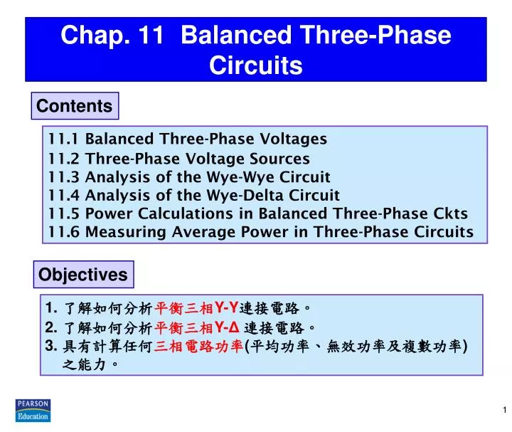
Chap.11 Balanced Three-Phase Circuits Contents 11.1 Balanced Three-Phase Voltages 11.2 Three-Phase Voltage Sources 11.3 Analysis of the Wye-Wye Circuit 11.4 Analysis of the Wye-Delta Circuit 11.5 Power Calculations in Balanced Three-Phase Ckts 11.6 Measuring Average Power in Three-Phase Circuits Objectives • 了解如何分析平衡三相Y-Y連接電路。 • 2. 了解如何分析平衡三相Y-Δ連接電路。 • 3. 具有計算任何三相電路功率(平均功率、無效功率及複數功率) • 之能力。
Practical Perspective • 為了經濟效益,對於大功率電力的產生、輸送、分配皆以 三相電路來完成。 • 三相系統的基本架構,是由電壓源經由變壓器及傳輸線連 接至負載。 • 三相電路電源與負載之連接方式有Y-Y, Y-Δ, Δ-Y及Δ-Δ 等連接方式。 2
11.1 Balanced Three-Phase Voltages 三相電壓: a 相電壓(a-phase voltage) b 相電壓(b-phase voltage) c 相電壓(c-phase voltage) abc 相序(abc phase sequence) 或 正相序(positive phase sequence) : b 相電壓落後a 相電壓120° c 相電壓領先a 相電壓120° 平衡三相電源:大小相同、頻率相同、相位角各差120o acb 相序(acb phase sequence) 或 負相序(negative phase sequence) : b 相電壓領先a 相電壓120° c 相電壓落後a 相電壓120° 3
11.2 Three-Phase Voltage Sources • 三相電源由三個分開的繞組所產生: Y 形接法及Δ 形接法。 • 中性端子(neutral terminal) : Y 形電源的共同端,接點n。 4
Three-Phase Source with Winding Impedances 三相電壓源及負載間有四種不同的接法 由於其他三種接法皆可化簡成Y-Y 等效電路,故而先行分析Y-Y 電路。 5
11.3 Analysis of the Wye-Wye Circuit • 圖示三相Y-Y系統,包含第四條導線連接電源與負載之中性端。 • Zga, Zgb, Zgc分別代表各相電壓源之內阻。 • Zla, Zlb, Zlc分別代表各相電源至負載之導線阻抗。 • ZA, ZB, ZC則代表各相負載阻抗。 平衡三相? 6
Conditions for a Balanced Three-phase Circuit 平衡三相電路各線路之電流 平衡三相電路的條件: 1. 電壓源Va'n, Vb'n, Vc'n構成一組平衡三相電源。 2. 每相電壓源之阻抗相同,亦即Zga = Zgb =Zgc。 3. 每相導線阻抗相同,亦即Z1a = Z1b = Z1c。 4. 每相負載阻抗相同,亦即ZA = ZB = ZC。 若為平衡三相電路 = 0 兩個中性端沒有電位差 中性導線電流=0 在平衡三相系統中,具有平衡的三相電流,所以一旦計算出IaA電流,就可直接寫出IbB, IcC之電流。 7
Single-phase Equivalent Circuit 負載端的線電壓VAB, VBC,VCA可用相電壓VAN, VBN,VCN來表示。 • 單相等效電路中之IaA並非平衡三相電路的中性導線電流,真正中性導線的電流為 • 當線電流IaA求出後,便可計算出其他的電壓。 8
Line-to-line Voltages &Line-to-Neutral Voltages • 線電壓之大小等於相電壓大小的倍 • 線電壓構成一組平衡三相電壓 • 線電壓組領先相電壓組30° abc(正)相序 abc(正)相序 Line-to-Neutral Voltages Line-to-line Voltages acb(負)相序 注意:若為acb(負)相序,則 線電壓組落後相電壓組30° 9
Line Voltage, PhaseVoltage, Line Current & Phase Current • 線電壓(line voltage):線與線之間的電壓 • 相電壓(phase voltage):指單相兩端的電壓 • 線電流(line current) :指單一線上的電流 • 相電流(phase current) :指單相內之電流 • 在Y型接法 線電流與相電流相同 線電壓 = line-to-line voltage 相電壓 = line-to-neutral voltage • 在型接法 • 線電壓與相電壓相同 • 相電壓 line-to-neutral voltage • 以表示單相的量,如: V, I, Z, P及Q分別代表每相之電壓、 電流、阻抗、實功率及無效功率。 10
EX 11.1 Analyzing a Y-Y Circuit a-phase equivalent 正相序 負相序 A balanced three-phase Y-connected generator with positive sequence has an impedance of 0.2 + j 0.5/ and an internal voltage of 120 V/ .The generator feeds a balanced three-phase Y-connected load having an impedance of 39 + j 28/. The impedance of the line connecting the generator to the load is 0.8 + j 1.5 / . The a-phase internal voltage of the generator is specified as the reference phasor. Construct the a- phase equivalent circuit of the system. b) Find IaA , IbB , and IcC. 11
EX 11.1 Analyzing a Y-Y Circuit (Contd.) 負相序 正相序 正相序 負相序 正相序 負相序 負相序 正相序 c) Find VAN , VBN , and VCN. d) Find VAB , VBC , and VCA. e) Find Van , Vbn , and Vcn. f) Find Vab , Vbc , and Vca. 12
11.4 Analysis of the Wye-Delta Circuit 平衡三相 -to-Y transformation a-phase equivalent 13
Line Currents &Phase Currents in abc(正)相序 Phase Currents • 線電流之大小等於相電流大小的倍 • 線電流構成一組平衡三相電流 • 線電流組落後相電流組30° abc(正)相序 Line Currents acb(負)相序 注意:若為acb(負)相序,則 線電流組落後相電流組30° 14
EX 11.2 Analyzing a Y- Circuit Y TheY-connected source feeds a -connected load through a distribution having an impedance of 0.3 + j 0.9/. The load impedance is 118.5 + j 85.8 / . Use the a-phase internal voltage as the reference. The a-phase equivalent b) The line currentsIaA , IbB & IcC c) The phase voltages at the load terminals 15
EX 11.2 Analyzing a Y- Circuit (Contd.) d) The phase currents of the load Check! e) Theline voltages at the source terminals 16
11.5 Power Calculations in Balanced Three-Phase Circuits Average Power in a Balanced Wye Load 17
Instantaneous Power in a Three-Phase Circuit 若以線至中性點瞬時電壓vAN為參考,且為正相序,為相位角差,各單相的瞬時功率可表示為pA, pB, pC,總瞬時功率pT為三者之和。 20
EX 11.3 Calculating Power in a Three-Phase Y-Y Circuit Check! Consider thecircuit described in EX 11.1 . a) The average power per phase deliveredto the load d) The total internal power lost in the generator e) The total number of magnetizing vars absorbedby the load 或 b) The total average power delivered to the load f) The total complex power delivered by the source 或 c) The total power lost in the line 21
EX 11.4 Calculating Power in a Three-Phase Y- Circuit Consider thecircuit described in EX 11.2 . a) The total complex power deliveredto the-connected load From EX 11.2 b)The percentage of the average power reachingthe load 22
EX 11.5 Three-Phase Power with an Unspecified Load A balanced three-phase load requires 480 kW at a lagging power factor of 0.8. The load is fed from a line having an impedance of 0.005 + j 0.025/. The line voltage at the terminals of the load is 600 V. The a-phase equivalent b) The magnitude of the line currents 或 23
EX 11.5 Three-Phase Power with an Unspecified Load (Contd.) c) The magnitude of the line voltage atthe sending end of the line d) The power factor atthe sending end of the line 或 24
11.6 Measuring Average Powerin Three-Phase Circuits • 用來測量三相電路功率的基本儀表,稱為電動力瓦特表(electrodynamometer wattmeter),內含兩個線圈,一為電流線圈(current coil),通過此線圈之電流與負載電流成正比;另一個稱為電壓線圈(potential coil),通過此線圈之電流與負載電壓成正比。 • 瓦特計指針的偏轉量與通過電流線圈電流有效值、電壓線圈兩端電壓有效值、電流和電壓間相角的餘弦值三者之乘積成正比。 右圖由n 條導線供應功率的一般網 路,以n為參考電壓點,其總功率 p = v1i1 +v2i2 + … + vn-1in-1。 對三相平衡電路而言,因為中性線沒有電流通過,故只需兩個瓦特計,即可量測總功率。 25
The Two-Wattmeter Method • 兩個瓦特計量測功率之特性: • 若功率因數大於0.5 時,兩個瓦特計皆是正值。 • 若功率因數等於0.5 時,其中一個瓦特計的值為零。 • 若功率因數小於0.5 時,其中一個瓦特計為負值。 • 當相序相反時,則兩個瓦特計之量測值剛好對換。 VCB 正向序 26
EX 11.6 Computing Wattmeter Readings in Three-Phase Circuits Calculate the reading of each wattmeter in the previous circuit if the phase voltage at the load is 120 V and (a) Z = 8 + j 6 ;(b)Z = 8 j 6 ; (c) Z = 5+j5√3 ; and (d) Z = 10∠−75◦. c) a) d) b) Check! 27
Transmission and Distribution of Electric Power 變電所三相的實功率為3.6 MW,無效功率為3.6 MVAR,線電壓為13.8 KV,配電線阻抗為0.6 + j 4.8 。 若電力系統必須將電壓準位維持在公稱值(nominal value) 之5.8 % 範圍內,則代表發電廠之線電壓範圍應介於13 kV 至14.6 kV 之間。 利用連接於變電所之電容器提供無效功率 28