Download
1 / 29
290 likes | 556 Views
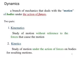
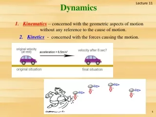
Dynamics. Dynamics. relationship between the joint actuator torques and the motion of the structure Derivation of dynamic model of a manipulator Simulation of motion Design of control algorithms Analysis of manipulator structures Method based on Lagrange formulation. Lagrange Formulation.

E N D
Dynamics • relationship between the joint actuator torques and the motion of the structure • Derivation of dynamic model of a manipulator • Simulation of motion • Design of control algorithms • Analysis of manipulator structures • Method based on Lagrange formulation
Lagrange Formulation • Generalized coordinates • n variables which describe the link positions of an n-degree-of-mobility manipulator • The Lagrange of the mechanical system
Lagrange Formulation • The Lagrange of the mechanical system Function of generalized coordinates Potential energy Kinetic energy
Lagrange Formulation • The Lagrange’s equations • Generalized force • Given by the nonconservative force • Joint actuator torques, joint friction torques, joint torques induced by interaction with environment
Actuation torque Reduction gear ratio Rotor inertia Viscous friction Stator is fixed on the previous link Initial position Lagrange Formulation Example 4.1 Generalized coordinate? Kinetic energy? Potential energy?
Lagrange Formulation Example 4.1 • Generalized coordinate: theta • Kinetic energy • Potential energy
Lagrange Formulation Example 4.1 • Lagrangian of the system
Lagrange Formulation Example 4.1 • Contributions to the generalized force • Dynamic of the model • Relations between torque and joint position, velocity and acceleration
Mechanical Structure • Joint actuator torques are delivered by the motors • Mechanical transmission • Direct drive
Computation of Kinetic Energy • Consider a manipulator with n rigid links Kinetic energy of the motor actuating joint i. The motor is located on link i-1 Kinetic energy of link i
Kinetic Energy of Link • Kinetic energy of link i is given by
Kinetic Energy of Link • Kinetic energy of a rigid body (appendix B.3) translational rotational
Kinetic Energy of Link • Translational • Centre of mass
Rotational • Inertia tensor
Inertia tensor is constant when referred to the link frame (frame parallel to the link frame with origin at centre of mass) Constant inertia tensor Rotation matrix from link i frame to the base frame
Kinetic Energy of Link • Express the kinetic energy as a function of the generalized coordinates of the system, that are the joint variables
Apply the geometric method for Jacobian computation to the intermediate link
Kinetic Energy of Motor • Assume that the contribution of the stator is included in that of the link on which such motor is located • The kinetic energy to rotor i
On the assumption of rigid transmission • According to the angular velocity composition rule Angular position of the rotor
attention • Kinetic energy of rotor
Computation of Potential Energy • Consider a manipulator with n rigid links
Equations of Motion • For the acceleration terms • For the quadratic velocity terms • For the configuration-dependent terms
Joint Space Dynamic Model Viscous friction torques Actuation torques Coulomb friction torques Force and moment exerted on the environment Multi-input-multi-output; Strong coupling; Nonlinearity