Download
1 / 32
320 likes | 552 Views
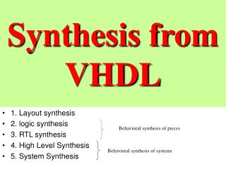
ECE 551 - Digital System Design & Synthesis Lecture Set 6 - Synthesis Overview. *Synthesis Flows *Internal Synthesizer Flow *Details of Synthesis Steps Other Synthesis Levels Benefits of Synthesis Synthesis Methodology Vendor Support

E N D
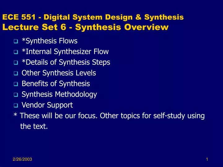
ECE 551 - Digital System Design & SynthesisLecture Set 6 - Synthesis Overview • *Synthesis Flows • *Internal Synthesizer Flow • *Details of Synthesis Steps • Other Synthesis Levels • Benefits of Synthesis • Synthesis Methodology • Vendor Support * These will be our focus. Other topics for self-study using the text.
Synthesis Flow • Oriented toward Synopsys Design Compiler • High-Level Design Flow (from Synopsys Design Compiler User Guide) • Design Methodology (from Synopsys HDL Compiler for Verilog) • Internal Synthesizer Flow
Technology Mapping Multi-Level Logic Optimization Parsing and Syntax & Semantic Error Checking Translation (Elaboration) Synthesizer Policy Checking Architectural Optimization Structural Representation Technology-Based Implementation Technology Library Internal Synthesizer Flow HDL Description
Initial Steps • Parsing for Syntax and Semantics Checking • Gives error messages and warnings to user • User may modify the HDL description in response • Synthesizer Policy Checking • Check for adherence to allowable language constructs and usage recommendations.
Translation (Elaboration) • Builds a structural representation of the design • This is net list like, but includes larger components • Gives additional errors or warnings to the user • Problems are not syntax or semantics of the language, but issues in initial transformation to hardware. • Affects the quality achieved by optimization steps • Structural representation depends on HDL quality • Poor HDL can lock solutions in undesirable design space for successful optimization
Architectural Optimization • May not be present in all synthesis tools • Examples: • Replace an adder with fixed inputs with an incrementer • Replace adder and subtractor with adder/subtractor if not used simultaneously • Performs selection of pre-designed components (Synopsys DesignWare)
Multi-level Logic Optimization • Minimization of two-level single output functions followed by: • Minimization of multi-level, multiple output functions
Minimization of Two-Level Single-Output Functions • Typically a near-optimal or optimal alteration of the “textbook” procedures covered in beginning logic design courses. Multi-level logic optimization • Example: Espresso from UCB • Starts from given 2-level expression representation and manipulates it to get an alternative representation with a lower literal count.
Minimization of Two-Level Single-Output Functions (Continued) • Heuristic Minimization • Operators • Expand - forms a prime and minimal cover with respect to single implicant containment - Each non-prime implicant is expanded to a prime and all other implicants covered by the expanded implicant are deleted.
Minimization of Two-Level Single-Output Functions (Continued) • Expand Example: C B B A A D D
Minimization of Two-Level Single-Output Functions (Continued) • Operators • Reduce - Transforms a cover into a non-prime cover. Attempts to replace each implicant with another contained in it while still covering the function.
Minimization of Two-Level Single-Output Functions (Continued) • Reduce Example: C B B A A D D
Minimization of Two-Level Single-Output Functions (Continued) • Operators • Reshape - Transforms a cover without changing the number of implicants. Expands one implicant while reducing another while still covering the function.
Minimization of Two-Level Single-Output Functions (Continued) • Reshape Example: C B B A A D D
Minimization of Two-Level Single-Output Functions (Continued) • Operators • Irredundant - A minimal subset of implicants is selected such that no single implicant in that subset is covered by the remaining ones.
Minimization of Two-Level Single-Output Functions (Continued) • Irredundant Example: C B B A A D D
Espresso Concept Expand Irredundant Iterate on: Reduce Expand Irredundant with heuristic switching inside operators
Optimization of Multiple Output, Multi-Level Functions • For minimization of two-level single -output functions, minimal cover minimizes both area and delay. • For multiple output, multi-level functions, there is a tradeoff between area and delay yielding the “banana” curve. • Optimization methods applied for: • Area minimization (under delay constraints) • Delay minimization (under area constraints)
Optimization of Multiple Output, Multi-Level Functions • Example multiple output, multi-level function logic network: w v = a’d +bd + c’d + ae’ a s = r + b’ b x r = p + a’ p = ce + de c t = ac + ad + bc + bd + e y d e u = q’c + qc’ + qc z q = a + b Connections not shown here.
Optimization of Multiple Output, Multi-Level Functions • Transformations (Operators) • Elimination - Removal of an internal vertex from a network.
Optimization of Multiple Output, Multi-Level Functions • Transformations (Operators) • Elimination Example: w v = a’d +bd + c’d + ae’ a s = p + a’ + b’ b x p = ce + de c t = ac + ad + bc + bd + e y d e u = q’c + qc’ + qc z q = a + b Connections not shown here.
Optimization of Multiple Output, Multi-Level Functions • Transformations (Operators) • Decomposition - Replacement of a vertex by two (or more) vertices that form a subnetwork equivalent to the original vertex.
Optimization of Multiple Output, Multi-Level Functions • Transformation (Operators) • Decomposition Example: w j = a’ + b + c’ v = jd + ae’ a s = r + b’ b x r = p + a’ p = ce + de c t = ac + ad + bc + bd + e y d e u = q’c + qc’ + qc z q = a + b Connections not shown here.
Optimization of Multiple Output, Multi-Level Functions • Transformations (Operators) • Extraction - factoring out of a common subexpression from two vertex functions to create a new vertex.
Optimization of Multiple Output, Multi-Level Functions • Transformations (Operators) • Extraction Example: w v = a’d +bd + c’d + ae’ a s = r + b’ b x r = p + a’ p = ke c t = ka + kb + e k = c + d y d e u = q’c + qc’ + qc z q = a + b Connections not shown here.
Optimization of Multiple Output, Multi-Level Functions • Transformations (Operators) • Simplification - Vertex function reduced in complexity by exploiting the properties of its representation.
Optimization of Multiple Output, Multi-Level Functions • Transformations (Operators) • Simplification Example: w v = a’d +bd + c’d + ae’ a s = r + b’ b x r = p + a’ p = ce + de c t = ac + ad + bc + bd + e y d e u = q + c z q = a + b Connections not shown here.
Optimization of Multiple Output, Multi-Level Functions • Transformations (Operators) • Substitution - Vertex function reduced in complexity by adding an input not previously in its set of inputs.
Optimization of Multiple Output, Multi-Level Functions • Transformations (Operators) • Substitution Example: w v = a’d +bd + c’d + ae’ a s = r + b’ b x r = p + a’ p = ke c t = kq + e k = c + d y d e u = q’c + qc’ + qc z q = a + b Connections not shown here.
Optimization of Multiple Output, Multi-Level Functions • Approaches: • Algorithmic - defines an algorithm for each transformation type which detects when and where the transform can be applied. • Rule-based - transformations of different types can be alternated according to a set of rules that mimic the optimization steps performed bya human designer.
Technology Mapping • Inputs are: • Optimized logic netlist • Available components from technology library • May include not only primitive gates, but • AOIs, OAIs, • Adders, subtractors, etc. • Output is: • Netlist in terms of components from technology library • Components may be shared if mutually exclusive use
References • De Micheli, G., Synthesis and Optimization of Digital Circuits, McGraw-Hill, 1994. • Devadas, S., A. Ghosh, and K. Keutzer, Logic Synthesis, McGraw-Hill, 1994. • Synopsys On-line Documentation and Manuals • Cilleti, M., Modeling, Synthesis and Rapid Prototyping with the Verilog HDL, Prentice Hall, 1999.