Download
1 / 43
430 likes | 500 Views
Detailed guide on installing and validating a reciprocating compressor in a machine shop for research and educational purposes. Includes engineering specifications, installation instructions, concept selection, risk assessment, and future plans.

E N D
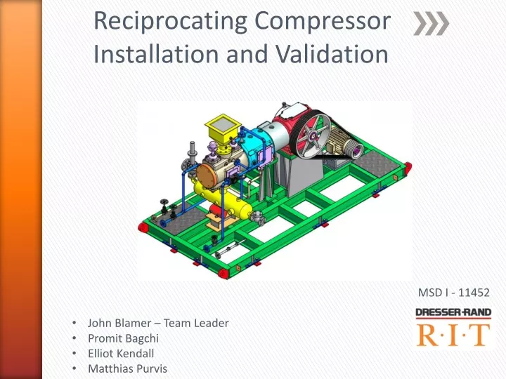
Reciprocating Compressor Installation and Validation MSD I - 11452 • John Blamer – Team Leader • Promit Bagchi • Elliot Kendall • Matthias Purvis
Agenda • Background – 2 min. • Project scope – 2 min. • Deliverables – 2 min. • Customer Needs – 3 min. • Objective Tree - 3 min. • Engineering Specifications – 2 min. • House of Quality – 2 min. • Ranked Engineering Specs – 2 min. • IPO (Input-Process-Output) – 4 min. • Installation – 8 min. • Delivery • Completed Tasks & Current state • Tasks to be Completed • Checklists • Concept Selection – 20 min. • Vibration Reduction • Mount Method, Adapter Plate • Calculations • Coolant System • Calculations • Risk Assessment – 4 min. • Future Plan - 4 min.
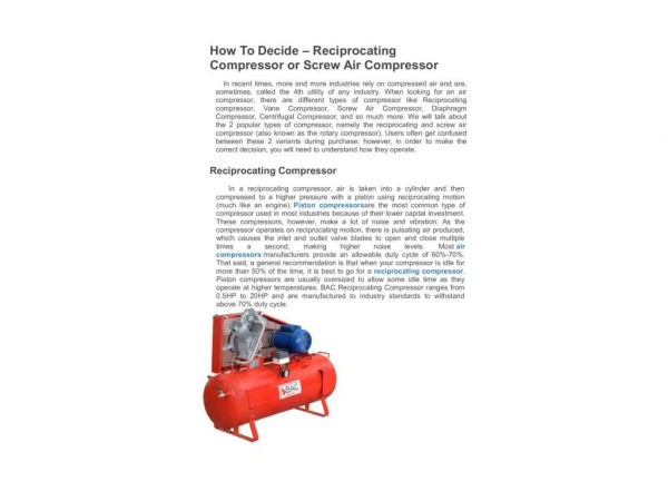
Background • Continuation of SD group P09452 • Reciprocating Compressor donated to RIT by Dresser-Rand • To be installed in Machine Shop • For Research and Educational purposes • P09452 did significant preparation work • Shipped from D-R facility in India • Should arrive in Port of New York on October 25th • Trucked to Boulter Rigging -> RIT
Project Scope • Understand compressor • Basic operation • Hardware • Understand installation needs • Vibration isolation • Cooling system • After install, focus on education and Beginning of Life characterization
Deliverables • Have the reciprocating compressor fully functioning by the end of Fall quarter • Implement a preliminary DAQ system already owned by RIT • Measure/document beginning of life characterization data for the compressor • Review, test, and validate the Thermodynamics and Vibration labs created by P09452
IPO (Input, Process, Output) – Broad Overview Outputs Inputs Ease of use Customer Needs Process Validation tests Fully functional compressor Delivery Beginning of life characteristics DAQ system Implementation Installation Education
IPO (Input, Process, Output) – Detailed View Outputs Inputs Ease of use User Manual Customer Needs Dr. Kolodziej Dr. Hensel Process Validation tests Dresser-Rand RIT faculty Fully functional compressor Boulter Delivery Beginning of life characteristics DAQ system Implementation Failure Diagnostics Installation Vibrations Lab Attach dampers to unit & bolt to floor E-Stops & Electricity Thermal Fluids Lab Education Cooling System Future Labs Lattice dampers In-Class Uses Electrician LORD Corp. RIT FMS Demonstration/Discussion Assignments System Analysis & Research Review & validate previous project
Installation – Delivery Plan • Work with Boulter Rigging • Dresser-Rand → Boulter Rigging → RIT • 45’ of transportation through Building 09 • Ensure a clear path • Load must be distributed over 60ft2 using skates
Installation – Completed Tasks • HVAC - Installed • Supply Ductwork • Exhaust • Electrical Components - Installed • Supply Box • E-Stop Button • Electrical Receptacles on each wall • Light Switches • Coolant System – Installed • U-Tube Heat Exchanger • Chilled Water Supply & Return • Delivery Preparation - Complete • Entrance Path Selected • Structural Reinforcement
Installation – Current State • Electrical • Ventilation • U-Tube Heat Exchanger
Installation – Tasks to be Completed • Vibration Isolation System • Finalize mounting system design. • Coolant System • Coolant System Design Finalization • Acquire and Install: • Pump • Piping • Reservoir • Heating Element • Thermostatic Valve • Flow Control Valve
Installation - Checklists • Pre-Arrival Checklist • Order cooling system components and hardware • Fabricate damper adapter plates • Contact Boulter to verify delivery procedures and schedule • Contact and verify past PE work • Post-Arrival Checklist • Drill mounting holes in skid • Thorough visual inspection for damages or abnormalities • Cooling system installation • Verify compressor specs (hp, discharge psi, etc.)
Concept Selection – Vibration Isolation Primary Options Option 1: Bolt unit directly to floor Option 2: Place directly on floor Compressor Frame Compressor Frame Shop Floor Shop Floor Bolt Option 3: Place unit on concrete slab and rubber mat Option 4/5: Mount to vibration dampers Compressor Frame Compressor Frame Concrete Slab Shop Floor Rubber Mat Shop Floor Vibration Mounts Bolt
Concept Selection – Vibration Isolation Secondary Options Option 6: Shock and Spring Option 7: Recycled Tire Mounts Compressor Frame Compressor Frame Shop Floor Shop Floor Option 8: Auto Motor Mounts Option 9: Hockey Pucks Compressor Frame Compressor Frame Shop Floor Shop Floor
Concept Selection - Vibration Isolation Preferred Method
Concept Selection – Mount Adapter Plate for LORD dampers Bolt adapter plate to I-Beam I-Beam Web Bolt holes to floor Bolt adapter plate to damper
Concept Selection – Mount Adapter Plate for LORD dampers Compressor Frame Adapter Plate LORD Damper To be drilled and bolted to frame
Concept Selection – Cooling System Layout #1: Immersion Heater Immersion Heater
Concept Selection – Cooling System • Layout #2: No Heater
Concept Selection – Cooling System • Layout #3:Heater Wrap Heater Wrap
Concept Selection – Cooling System • Layout #4: In-Line Heater In-Line Heater
Concept Selection – Cooling System In Line Heater No Heater Immersion Heater Net Score
Component Selection – Heating Element • Assumptions: • 10 degrees temperature rise • Four gallon reservoir
Concept Selection– Cooling System Flexible Plastic Copper
Component Selection – Cooling System • ¾” Silicone Tubing • Pump • 3 way Thermostatic Valve