Download
1 / 57
570 likes | 793 Views
Layers. Layering Mechanisms. Introduction to layering design principles Determining when to use layers The attention points when layering Layering and PAC model. Layered Systems. Hierarchically organised A layer provides services to layer(s) above it

E N D
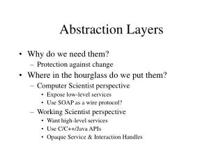
Layering Mechanisms • Introduction to layering design principles • Determining when to use layers • The attention points when layering • Layering and PAC model
Layered Systems • Hierarchically organised • A layer provides services to layer(s) above it • A layer is a client to layer(s) below it • Possible topological constraints (opaqueness) • Limit interactions between adjacent layers
Examples of layered Systems • Layered communication protocols (e.g. OSI) • OS kernels (e.g. Windows, Chorus) • Database systems (e.g. ANSI/SPARC) • Many commercial apps use layers model • The agents in a PAC model!
Generic OS Environment • User-visible elements (layer 6) • Specific application modules (layer 5) • Common services level (layer 4) • OS interface level (layer 3) • OS (may itself be layered) (layer 2) • Hardware (layer 1)
Reasons for layered Systems • Support designs based in increasing levels of abstraction • Can partition a problem into smaller pieces • Changes to a layer affect only a few layers • Layers can be used interchangeably • Reuse is supported
Implementing layered Systems • We use Buschmann’s Layers pattern • Iterative process in general (‘yo-yo’) • Approximately 10 steps • Other (Gamma) patterns may be used • Approach is reusable (RT UML, component technology)
Some Definitions • A task is a responsibility of a given layer • A service is a set of functions offered by a layer • We speak of service layering • Each layer has interface functions • A layer can be implemented as a Black Box or White Box
More on Services • Each layer can be viewed as a virtual machine • A service is a programmable facility of a virtual machine • Examples of services: DB, comm, UI
What is ‘inside’ a Layer? • A layer populated by modules (e.g. objects) • Determine how to access module interfaces • Two main possibilities • 1: ability to access all objects (White Box) • 2: create a ‘contact’ for all modules (Black Box)
What is a Black Box? • Layer N is a black box for layer N + 1 • Design a flat interface that offers layer N’s services • This can be achieved by the Façade pattern • Necessitates introduction of a Façade object
Consequences of Black Box Approach • Supports system evolution • Can support multiple interface implementations (see Bridge pattern) • May not be the most efficient approach • Adds to project time
What is a White Box? • Layer N + 1 sees internals of layer N • Upper layer may access modules in layer N • Introduces explicit coupling • Compromise: ‘gray’ box
What is a Gray Box? • Something between White and Black! • Layer N + 1 knows number of components in layer N • Each component is addressed separately • However, it does not know about component internals
Consequences of White Box Approach • Relatively easy to implement • Incremental development • Large maintenance costs • Low reusability levels
Layers: Steps Part I • 1: Determine abstraction criteria for task grouping • 2: Determine the number of abstraction levels • 3: Name layers and assign tasks to them • 4: Specify layers’ services • 5: Refine the layering
Abstraction Criteria • Most difficult step during layering process • Determine the different tasks • Then groups tasks into layers • Iterative process • OOA use cases are of help here
ExamplePAC Model • Three layers and three major tasks • Task 1: Interactions with external environment • Task 2: Business objects and logic management • Task 3: Communication with other agents
Number of Abstraction Levels • Each abstraction level corresponds to 1 layer • Can split a layer into 2 layers • Layers can be combined • Associated advantages and disadvantages
ExamplePAC • Three layers (P, A, C) • Correspond to UML (B,E,C) pattern • Sufficient regime for many applications • In some cases we can split A into 2 layers • Then get a 4-layer regime
LayersNames and Responsibilities • Highest layer is overall system task • Other tasks are ‘helpers’ • Lower layers provide an ‘infrastructure’ • Higher layers use services of lower layers • Demands experience and foresight
ExamplePAC • Layer 1: SensorUnit (interaction with environment) • Layer 2: ModelledEntity (objects of interest) • Layer 3: Controller (dispatching/notification)
Services of Layers • High-level description of what a layer offers to upper layers • Keep services distinct • Locate more services in higher layers • This reduces programmer ‘cognitive overload’
Layer Refinement • Iterate over steps 1 to 4 • Combination of top-down and bottom-up approaches • Be careful not to destroy strict layering
ExampleMoving from PAC to Agent Technology • Agent technology uses a number of layered models • Can be seen as an extension of the OO model • A 4-layer regime is common
Prototypical 4-layer Model • Level 1: World interface layer (sensors) • Level 2: Behavioural layer (reactive objects) • Level 3: Planning layer (algorithms, proactive objects) • Level 4: Communication layer (group planning, communication with other agents)
Layers: Steps Part II • 6: Specify an interface for each layer • 7: Structure individual layers • 8: Specify communication between layers • 9: Decouple adjacent layers • 10: Design an error-handling strategy
Layer Interfaces • Problem of finding interfaces for each layer • Differences for white, black and gray boxes • Sequence diagrams help here • Possible to define and discover standard interfaces
Layer Structure • Objective is to structure the internals of each layer • Break a layer into finer components • Gamma patterns are useful at this level • Finer-grained structures
ExamplePAC • Bridge: support multiple implementations of a layer interface • Composite: complex aggregate objects • Strategy: dynamic interchange of algorithms in a layer • State: implementing state machines in an object
Inter-layer Communication • Determines how layers exchange information • Precondition is that they ‘know’ each other in some way • Choice depends on a number of factors
Determining the best Choice • Loose coupling (callbacks, implicit invocation) • Efficiency (peer-to-peer model) • Ability to switch at configuration time or run-time
Decouple adjacent Layers • Optimisation step, many options • Two-way or one-way coupling • Callbacks help one-way coupling • Use of C++ abstract classes • Use of Bridge pattern
Error-handling Strategy • Really a separate design/analysis issue • Has a major performance impact on layered systems • Handle error in current layer or hand it off to next layer? • Rule: handle errors at lowest possible layer
ExamplePAC • P: hardware errors (no response, heavy response) • A: emergency requests • C: notification errors
Advantages of Layering • Reuse of layers • Support for standardisation • Dependencies are kept local • Exchangeability of layers (via Bridge)
Disadvantages of Layering • Cascades of changing behaviour • Lower efficiency • Unnecessary work • Correct granularity of layers. What is it?
Layering and PAC: last Remarks • Similarities (levels of increasing abstraction) • PAC structure is a tree of PAC nodes • Layers is a vertical line of nodes • Each PAC node consists of three components • Layers does not prescribe how many layers to create
ExampleSteam-Boiler Problem • Well-known prototype problem • Objective here is to show how layers are implemented • Knowing what was done allows us to improve the code quality and flexibility • Three layers in general (based on PAC) • We concentrate on Delivery agent
Delivery • Responsible for producing heat and cold • Realised by physical actuators • Knows about provision of services • 3-layer agent
Abstraction Criteria • Desire to distance system from physical hardware • Locate interactions with hardware in one layer • Another layer knows what service is needed and what it can provide • Upper layer is responsible for communi-cating results and acknowledgements
Layer Names and Tasks • Delivery: 2-way dispatching/notification • ActuatorUnit: current service needs and resources • Actuators: Physical heating/cooling units • Names can be generalised (later)
Services • Each layer provides services to upper layer • Define service-access points (SAPs) and service provision points (SPPs) • SAP and SPP are closely related • SAP is ‘upper’ part, SPP is ‘lower’ part • SAP and SPP ensure that layers are uncoupled
Services • ActuatorControl: heat and cold regulation levels • Actuators: heat and cold regulation • Delivery: service requests • No layer refinement
Interfaces for Layers • C++ used • Interface functions based on sequence diagrams • White box approach • Tight coupling between layers (call and return mechanism)
Inter-layer communication • Realised by function calls • Layers know address of upper and lower neighbours • Return and call: all action starts in Mediator • We can call it a pull model
Decoupling Layers • Not done in this version of the software • Use of C++ inheritance and Event classes enhances loose coupling • use Command pattern to pass functions from layer to layer