Download
1 / 15
150 likes | 271 Views
Thermal management for ATLAS upgrade. Georg Viehhauser. Organisation. Common understanding that thermal management in ATLAS has been more painful than necessary. Thermal management comprises

E N D
Thermal management for ATLAS upgrade Georg Viehhauser
Organisation • Common understanding that thermal management in ATLAS has been more painful than necessary. • Thermal management comprises • High thermal conductivity materials (this is the aspect which did belong to subsystem designs and has worked out well), • Cooling (external plant and on-detector components like HEXs and heaters, services like pipes and fittings, etc.), • Environment (thermal enclosure, humidity incl. monitoring, etc.). • Attributed to absence of any coordinated management structure & lack of effort until late in production. • For upgrade: Thermal management working group established as first subgroup of the upgrade project office.
(Original) remit of the TMWG • Cooling technology • Quick agreement: go evaporative again • Various candidate coolants: Fluorocarbons (C3F8, C2F6) or CO2. • Address issues like • Control: Fixed vs variable mass flow. • Throttling • Pipework and Fitting specification • Test facility design and manufacture • During ATLAS assembly several C3F8 have been built in parallel with very different designs – duplicate efforts • Environment • Thermal enclosure • Humidity environment • Monitoring • Cooling system • Environment • Materials including thermal interfaces • This is now covered by the subdetector collaborations.
Key requirements • About 10°colder than present ATLAS ID(coolant temperature -35°C instead of -25°C) • ~2× power of present ATLAS ID(~100-150kW instead of 60kW), • increase in size and channel density, • but reduction of power per electronics channel. • About 800 supermodules/staves. • High reliability and robustness against failures. • Failures should not affect large sections of experiment. • Access to complex objects (HEXs, heaters, etc.)
Coolant options • C3F8 • By 2017 we have ~10y of operational experience. Reduce start-up hiccups if we can develop an adiabatic upgrade plan. • But: It is not clear that a pure C3F8 system can achieve the evaporation temperature. • Tevap = T(pevap) and pevap = psuction + Δppipe + Δpbpr • We have to address this already for the existing system. • Various strategies under consideration: • Lower psuction: surface condensers, multi-stage compressors, • Avoid Δpbpr: evaporation pressure control through cold condensers, • Lower T(pevap): Use C2F6/C3F8 mixtures. • CO2 • Expect smaller mass flow (large latent heat), smaller pipes (large HTC), albeit probably thicker wall. • Higher pressures (pmax ~50-100bara, pevap~10bara). • Not a fundamental problem, but needs careful engineering. • No danger of restricting environmental legislation. • Industry’s future coolant of choice. • The decision needs to be made soon (impact on detector design).
A major constraint for ATLAS upgrade Reuse existing services running from z=0 (outside calorimeters) to end of calorimeter to reduce shutdown time. • These services run underneath innermost μ layer, which should not be disturbed to shorten shutdown. • This has never been formally evaluated and decided (too complex), but became widely accepted. • This provides a limitation • In diameter and number (issue for C3F8: limits possible reduction in return line pressure drop). • Due to pressure specification (issue for CO2: present Cu/Vulkan Lokring pipework only good to 30 to 50bara). • Due to lack of insulation: • transfer pipes need to be warm (above dewpoint ~15°C), • conservative estimate: feed pipes @ 35°C due to environment (cables), • this increases the input vapour quality → reduces the available latent heat → increased system complexity (requires pre-cooling HEXs, requires heaters) and drives up the feed pressure for coolants with low critical pressure.
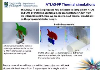
A possible solution: multi-stage system • Primary (plant) stage: • Conventional (oily?) Compressor-condensor-throttle-evaporator system. • Technology (coolant) is flexible. • This has warm transfer pipes (if CO2 with high feed pressure ~100 bara). • Evaporates at ~ -40°C. • Return lines have electrical heaters (accessible) to keep return fluid warm. • Secondary (detector) stage: • Condensor-pump-evaporator • This would have cold, low-pressure lines. • Condenses at ~ -40°C, evaporates at ~-35°C. • While in principle you don’t need a throttle (capillary), it will be required for control of the circuit and flow balancing. • To minimize mass flow (pipe diameter) the coolant in this stage will be CO2. • Thermally connected by HEX at PP2 • Throttling, back pressure regulation and heater close to HEX → accessible (~1d) and “moderate” radiation. Middle muon Access Inner muon Calorimeter ID Q Q detector Conceptual, not to scale Q
Pipework • In ATLAS • Poorly evaluated technologies and procedures, • Aluminium pipes: corrosion problems due to alloy choice and handling mistakes, • Home-made connections developing leaks. • Poorly specified leak-rate requirements, • Varying from section to section. • Learned a lot about QA too late • E.g. X-rays of welds etc. • Upgrade: • Develop a coherent set of specifications for all components, • Specifications for components where possible (base on industrial standards where possible), • Definition of specification procedures for new (homemade) solutions, • Ultimately possibly specifications of components (fittings, etc.), • This specifications (components and procedures) should be used at all stages of the project (design, assembly, commissioning, running), • This task is formidable, but could/should be of wider interest.
Risk analysis • In the past • Done late with insufficient resources and expertise • has been usually a fault mode analysis, not a risk analysis. → often retroactive, not part of design decisions. • Should be • Expanded to reliability analysis and as such should influence design. • Will need to learn a lot about this…
Future organization • So far there has been a split into present system and sLHC upgrade. • In the future there will be global ATLAS structure on cooling including • Current system operation, • Improvements to current system to reach ATLAS final specifications, • Cooling for the insertable B-layer (innermost Pixel), • ID cooling for sLHC upgrade. • Details are being worked out right now. Sharing of resources, brainpower and information needs to be organized.
Some cooling contacts in ATLAS Rather than listing all groups and individuals I will list a few contacts which then can guide you on. • Present system operation: Steve McMahon, Koichi Nagai, • C3F8 upgrades: Greg Hallewell, • CO2 cooling: Bart Verlaat, Nigel Hessey, • Pipes and connectors: Jason Tarrant, • CF pipes: Danilo Giugni.
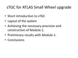
Carbon Dioxide: Pressure - Enthalpy Diagram Mode #1, Full Power 1,000 140 -20 40 120 160 100 20 60 80 t = 0 oC r = 1200 r = 600 r = 800 Density = 700 kg/m3 r = 1000 r = 1150 r = 500 r = 900 r = 1050 r = 1100 -40 -2.00 -.90 --1.60 -1.00 -1.70 -.80 -1.50 -1.90 -1.80 -1.30 -1.40 -1.10 -2.10 -1.20 s = -2.20 100 r = 100 Entropy = -2.30 kJ/kg,oC -.70 r = 75 Pressure, Bar Melting Line 10 -.30 Triple Point (5.18 bar, -56.558 oC) Sublimation Line 60 0 40 20 -20 1 350 400 450 500 550 600 650 700 750 800 850 Enthalpy, kJ/kg From Auke Colijn