Download
1 / 34
340 likes | 423 Views
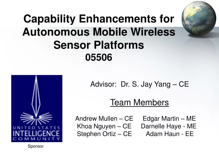
Capability Enhancements for Autonomous Mobile Wireless Sensor Platforms 05506. Advisor: Dr. S. Jay Yang – CE Team Members Andrew Mullen – CE Edgar Martin – ME Khoa Nguyen – CE Darnelle Haye - ME Stephen Ortiz – CE Adam Haun - EE. Sponsor. Presentation Overview. Project Goal

E N D
Capability Enhancements for Autonomous Mobile Wireless Sensor Platforms05506 Advisor: Dr. S. Jay Yang – CE Team Members Andrew Mullen – CE Edgar Martin – ME Khoa Nguyen – CE Darnelle Haye - ME Stephen Ortiz – CE Adam Haun - EE Sponsor
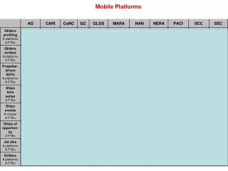
Presentation Overview • Project Goal • Design Objectives • Objectives • Task Groups Formed to Accomplish Objectives • Senior Design I Timeline • Chassis Design Process • Concepts and Prototypes • Electrical Design Process • Component Selection • Communication Implementation • Senior Design II Timeline • Questions?
Project Goal • Develop a set of four mobile wireless sensor platforms with the ability to autonomously communicate and make decisions, independent of a base station, to create formations
Design Objectives • Phase I • Design a cost effective and energy efficient chassis. • Determine an appropriate sensor configuration to facilitate identification of objects and locomotion. • Implement robust assembly code allowing the robots to move freely through their environment • Phase II • Integrate wireless communication allowing the robots to exchange information rapidly and effectively using the Mica2dot RF Transceivers. • Construct an additional Three Mobile Sensor Platforms • Develop and Code algorithms implementing formations
Task Groups • Darnelle Haye & Edgar Martin (MEs) • Develop Chassis Design • Fabrication and Assembly of Chassis • Stephen Ortiz & Khoa Nguyen (CEs) • Communication Interface • Wireless Software Development • Adam Haun (EE) & Andy Mullen (CE) • Circuit-board Layout and Design • Sensor Integration • Robot Intelligence Assembly Code
Senior Design I Timeline • First Quarter • Week 3: First Team Meetings, Performed Concept Development and began Feasibility Analysis • Week 4: Basic chassis fabricated, performed weight test • Week 5: Completed Feasibility Analysis, Began Implementation • Week 6: Second chassis, autonomous movement • Week 7: Improved Movement Commands to allow a more robust and modular Interface • Week 8: Integrated Sonar Sensor • Week 9: Began Planning for Demonstration • Week 10: Debug, perform demonstration
Chassis Design Concepts • Use a Pre-Built robotics kit or Custom Design • There are many kits to help novices design robots • Method Of Locomotion • Different Drive Systems (Differential, Synchro, Skid-Steer, Car-Type) • Pivot Point Options • Castor Wheel or Ball Bearing • Materials Selection
Feasibility Analysis Results • Three Tier Design • Chose to use 2 Stepper Motors • Utilizing Differential Drive • Ball Bearings • More effective than a Castor • Material - Acrylite FF Sheets • Lightweight , rigid, and weather-resistant thermoplastic. • Dimensionally stable, resistant to breakage, and can be easily sawed, machined, heat-formed and cemented
Initial Concepts -Does Not Rotate around Center of Mass -Inefficient Use of Space -Awkward -Not Enough Space for Components -Overly Heavy
Initial Prototypes -Used for weight test -Measured Maximum Load -Prototype Unacceptable For actual use -Circular shape saves weight -Makes Design more efficient -Space for Sensors -Location For Battery Pack
Current Chassis Design • Ball Bearing Integrated • Slight resize of platform levels
Mechanical Future Plans • Integrate a more efficient ball bearing which is better suited for the mobile platform’s design • Attach the compass chip to the chassis • Due to magnetic interference from the motors the compass chip must be at least 6 inches from a motor • Magnetic shielding may allow the compass sensor to be located closer to the rest of the electronics • Examine the platform for ways to reduce weight
Electronics & Sensor Concepts • PIC Microcontroller Selection • Motor Controller Selection • Distance Sensors • Infrared Sensors • Ultrasonic Sensors • Which is more effective? • Compass Sensor • Is one available which meets our needs and budget? • Power Supply • Rechargeable battery? Size? Weight? Power? • Universal Power Supply or Multiple Power Supplies
Feasibility Analysis Results • PIC-18F4320 Microcontroller • MC3479P & UC3770 Motor Controllers • Both will be tested, MC3479 has a simpler interface, UC3770 may be more effective • Front and Rear Ultrasonic Sensors • Devantech R93-SRF04 Ranger • Integrate Compass Sensor • Devantech R117-COMPASS • 9.6 Volt NiMh 1600 mAhr batteries • An LM317T is used to provide the 5V necessary to run the PIC, controller logic, and sensors. • 3.3V may be added in the future to power wireless motes
Microcontroller Capability • We used a PIC18F4320 to control the system. • The PIC provides sufficient I/O ports to control the motors and interface with any of the sensors the team examined. • Nearly 40 Input/Output Bits • 4 Independent Timers • Internal USART support • An internal clock speed of 8MHz gives the team plenty of extra processing power.
Initial Motor Controller(MC3479P) • Pros: Low current, compact • Cons: Weak, high heat
Current Motor Controller(UC3770AN) • Pros: High power, low heat • Cons: Requires two chips per motor and more complicated programming.
Sonar Sensor • Relatively narrow Beam Pattern • Linear Output • Highly Accurate • Range – 3 to 300 cm
Compass Sensor • Adds Global Direction to Sensor Platforms • Simplifies Algorithms • Senses to within 0.1 Degrees
Assembly Considerations • For the prototype, the main concern was the ability to easily change the circuit. A breadboard fills this need. However, the breadboard is unsuitable for the final robot because of its fragility and complexity. • For the final robot, we will order a printed circuit board. This will be more compact and allow for more secure mounting.
Communication Goals • Integrate the Mica2dot RF Transceiver with the main microcontroller. • Establish capabilities of Mica2Dot Wireless Motes. • Research Mica2 mote applications and proceed with execution on Mica2Dot motes. • Determine how the motes are processing messages (Packet Information) • Learn how to code NC programs to implement desired functionality on the Mica2Dot Motes • Establish Communication between Motes, by means of a base station controlled by PC to other motes • Develop an interface through which communication can be effectively established.
Mica2Dot Wireless Mote • Quarter-Sized (25mm), Wireless Platform for Smart Sensors • Designed Specifically for Deeply Embedded Wireless Sensor Networks • Battery-Powered • Lightweight
Mica2Dot Interface • The Mica2Dot has 18 solderless expansion pins • 6 Analog Inputs • 6 Digital I/O Channels • UART (Universal Asynchronous Receive Transmit) interface. • UART transmission will be used for direct communication from the Mica2Dot to the PIC chip.
Transmission Packet Information • Destination address (2 bytes) • Active Message handler ID (1 byte) • Group ID (1 byte) • Message length (1 byte) • Payload (up to 29 bytes): • Source Mote ID (2 bytes) • Sample Counter (2 bytes) • Transmission Information Readings (up to 25 bytes)
Mica2Dot Code • Written in NC (Network Channel) code. The code used to identify both switched and non-switched channel services. • NC coding is module C based code. A module header file is needed to define the wiring used by the module as well as determine the module’s interface. • The TinyOS operating system is Task Driven
Current Communication Progress • Radio Communication • Set up wireless communication and packet sending demonstrated by the red LED on a mote. One mote blinks an LED and sends packets to all other motes instructing them to blink their LED. • Injecting and broadcasting packets sent by a Base Station • Injected packets from a PC into the sensor network by means of Led_on and Led_off commands. Base Station mote broadcasts messages to receiving motes. RS-232 Cable
Communication Future Plans • Establish communication allowing a variable number of motes to send, process, and receive information without interference. • Eliminate base station control to allow each sensor platform to remain autonomous • Write code to visually log the information sent by the Mica2Dot motes on a computer terminal.
System Integration Challenges • Difficult to Debug if Errors Occur • All Code done in assembly • No effective debugging tool because of sensor input • Mica2Dot Motes • TinyOS installation and configuration is complex • UART Transmission difficult to test • CE computer virus • Sonar Sensors • Can’t display distance easily • Difficult to manipulate received data