Download
1 / 35
390 likes | 1.32k Views
BEAMS. SHEAR AND MOMENT. Beam Shear. Shear and Moment Diagrams Vertical shear: tendency for one part of a beam to move vertically with respect to an adjacent part . Beam Shear. Magnitude (V) = sum of vertical forces on either side of the section

E N D
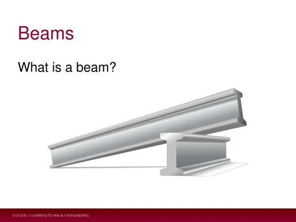
BEAMS SHEAR AND MOMENT
Beam Shear • Shear and Moment Diagrams • Vertical shear: tendency for one part of a beam to move vertically with respect to an adjacent part
Beam Shear • Magnitude (V) = sum of vertical forces on either side of the section • can be determined at any section along the length of the beam • Upward forces (reactions) = positive • Downward forces (loads) = negative • Vertical Shear = reactions – loads (to the left of the section)
Beam Shear • Why? • necessary to know the maximum value of the shear • necessary to locate where the shear changes from positive to negative • where the shear passes through zero • Use of shear diagrams give a graphical representation of vertical shear throughout the length of a beam
Beam Shear – • Simple beam • Span = 20 feet • 2 concentrated loads • Construct shear diagram
Beam Shear – Example 1 • Determine the reactions Solving equation (3): Solving equation (2): Figure6.7a =>
Beam Shear – Example 1 (pg. 64) • Determine the shear at various points along the beam
Beam Shear – Example 1 • Conclusions • max. vertical shear = 5,840 lb. • max. vertical shear occurs at greater reaction and equals the greater reaction (for simple spans) • shear changes sign under 8,000 lb. load • where max. bending occurs
Beam Shear – Example 2 • Simple beam • Span = 20 feet • 1 concentrated load • 1 uniformly distr. load • Construct shear diagram, designate maximum shear, locate where shear passes through zero
Beam Shear – Example 2 • Determine the reactions Solving equation (3): Solving equation (2):
Beam Shear – Example 2 • Determine the shear at various points along the beam
Beam Shear – Example 2 • Conclusions • max. vertical shear = 11,000 lb. • at left reaction • shear passes through zero at some point between the left end and the end of the distributed load • x = exact location from R1 • at this location, V = 0
Beam Shear – Example 3 • Simple beam with overhanging ends • Span = 32 feet • 3 concentrated loads • 1 uniformly distr. load acting over the entire beam • Construct shear diagram, designate maximum shear, locate where shear passes through zero
Determine the reactions Solving equation (3): Solving equation (4):
Beam Shear – Example 3 • Determine the shear at various points along the beam
Beam Shear – Example 3 • Conclusions • max. vertical shear = 12,800 lb. • disregard +/- notations • shear passes through zero at three points • R1, R2, and under the 12,000lb. load
Bending Moment • Bending moment: tendency of a beam to bend due to forces acting on it • Magnitude (M) = sum of moments of forces on either side of the section • can be determined at any section along the length of the beam • Bending Moment = moments of reactions – moments of loads • (to the left of the section)
Bending Moment – Example 1 • Simple beam • span = 20 feet • 2 concentrated loads • shear diagram from earlier • Construct moment diagram
Bending Moment – Example 1 • Compute moments at critical locations • under 8,000 lb. load & 1,200 lb. load
Bending Moment – Example 2 • Simple beam • Span = 20 feet • 1 concentrated load • 1 uniformly distr. Load • Shear diagram • Construct moment diagram
Bending Moment – Example 2 • Compute moments at critical locations • When x = 11 ft. and under 6,000 lb. load
Negative Bending Moment • Previously, simple beams subjected to positive bending moments only • moment diagrams on one side of the base line • concave upward (compression on top) • Overhanging ends create negative moments • concave downward (compression on bottom)
Negative Bending Moment • deflected shape has inflection point • bending moment = 0 • See example
Negative Bending Moment - Example • Simple beam with overhanging end on right side • Span = 20’ • Overhang = 6’ • Uniformly distributed load acting over entire span • Construct the shear and moment diagram • Figure 6.12
Negative Bending Moment - Example • Determine the reactions • Solving equation (3): • Solving equation (4):
Negative Bending Moment - Example 2) Determine the shear at various points along the beam and draw the shear diagram
Negative Bending Moment - Example 3) Determine where the shear is at a maximum and where it crosses zero • max shear occurs at the right reaction = 6,540 lb.
Negative Bending Moment - Example 4) Determine the moments that the critical shear points found in step 3) and draw the moment diagram
Negative Bending Moment - Example 4) Find the location of the inflection point (zero moment) and max. bending moment • since x cannot =0, then we use x=18.2’ • Max. bending moment =24,843 lb.-ft.
Rules of Thumb/Review • shear is dependent on the loads and reactions • when a reaction occurs; the shear “jumps” up by the amount of the reaction • when a load occurs; the shear “jumps” down by the amount of the load • point loads create straight lines on shear diagrams • uniformly distributed loads create sloping lines of shear diagrams
Rules of Thumb/Review • moment is dependent upon the shear diagram • the area under the shear diagram = change in the moment (i.e. Ashear diagram = ΔM) • straight lines on shear diagrams create sloping lines on moment diagrams • sloping lines on shear diagrams create curves on moment diagrams • positive shear = increasing slope • negative shear = decreasing slope
Typical Loadings • In beam design, only need to know: • reactions • max. shear • max. bending moment • max. deflection