Download
1 / 37
800 likes | 3.39k Views
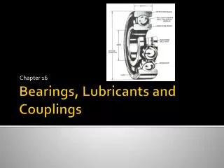
Chapter 11 - Keys, Couplings and Seals. 11.1 Chapter Objectives:. How attach power transmission components to shaft to prevent rotation and axial motion? Torque resistance: keys, splines, pins, weld, press fit, etc..

E N D
Chapter 11 - Keys, Couplings and Seals 11.1 Chapter Objectives: • How attach power transmission components to shaft to prevent rotation and axial motion? • Torque resistance: keys, splines, pins, weld, press fit, etc.. • Axial positioning: retaining rings, locking collars, shoulders machined into shaft, etc…. • What is the purpose of rigid and flexible couplings in a power transmission system? • Specify seals for shafts and other types of machine elements.
11.2 Keys • Most common for shafts up to 6.5” is the square and rectangular keys: • Cost effective means of locking the • Can replace damaged component • Ease of installation • Can use key as “fuse” – fails in shear at some predetermined torque to avoid damaging drive train. Advantages: Figure 11.1
Square and rectangular keys: Step 1 – Determine key size based on shaft diameter Step 2 – Calculate required length, L, based on torque (11.4)
Step 3 – Specify appropriate shaft and bore dimensions for keyseat: See Figure 11.2 For 5/16” key SHAFT BORE Note, should also specify fillet radii and key chamfers – see Table 11-2
Other types of keys: • Tapered key – can install after hub (gear) is installed over shaft. • Gib head key – ease of extraction • Pin keys – low stress concentration • Woodruff key – light loading offers ease of assembly
11.4 Design of Keys – stress analysis to determine required length: = Torque being transmitted No load T = F/(D/2) or F = T/(D/2) this is the force the key must react!!!
Bearing stress Shear stress Required Length based on Bearing Stress: Required Length based on Shear Stress: Typical parameters for keys: N = 3, material 1020 CD (Sy = 21,000 psi)
Example: Specify the complete key geometry and material for an application requiring a gear (AISI OQT 1000) with a 4” hub to be mounted to a 3.6” diameter shaft (AISI 1040 CD). The torque delivered through the system is 21,000 lb-in. Assume the key material is 1020 CD (Sy = 21,000 psi) and N = 3. Solution (note since key is weakest material, focus analysis on key!): See handout
11.4 Splines • Advantages: • Can carry higher torque for given diameter (vs keys) or • Lower stress on attachment (gear) • Better fit, less vibration (spline integral to shaft so no vibrating key) • May allow axial motion while reacting torque • Disadvantage: • Cost • Impractical to use as fuse
Splines “Axial keys” machined into a shaft Transmit torque from shaft to another machine element
Advantages • Uniform transfer of torque • Lower loading on elements • No relative motion between “key” and shaft • Axial motion can be accommodated (can cause fretting and corrosion) • Mating element can be indexed with a spline • Generally hardened to resist wear
Spline Types • Straight • SAE • 4, 6, 10 or 16 splines • Involute • Pressure angles of 30, 37.5, or 45 deg. • Tend to center shafts for better concentricity
SAE Spline Sizes A: Permanent Fit B: Slide without Load C: Slide under Load Pg 504
Two types of splines: Straight Sided Involute:
Use this for spline design – SAE formulas based on 1,000 psi bearing stress allowable!! Use this to get diameter. Then table 11.4 to get W, h, d
Torque Capacity • Torque capacity is based on 1000 psi bearing stress on the sides of the splines T = 1000*N*R*h N = number of splines R = mean radius of the splines h = depth of the splines
Torque Capacity Cont’d Substituting R and h into torque equation:
Torque Capacity Cont’d • Further refinement can be done by substituting appropriate values for N and d. • For 16 spline version, with C fit, N = 16 and d = .810D Torque in IN-LBS/INCH of spline Required D for given Torque
Example: A chain sprocket delivers 4076 in-lbs of torque to a shaft having a 2.50 inch diameter. The sprocket has a 3.25 inch hub length. Specify a suitable spline having a B fit. T = kD2L T = torque capacity in in-lbs kD2 = torque capacity per inch (from Table 11-5) L = length of spline in inches
Example Continued • From Table 11-5, use 6 splines
2.5 4076/3.25 Torque Capacity for Straight Splines
Example: Specify straight spline for the previous problem (i.e. Torque = 21,000 lb-in and shaft is 3.6 in diameter.
Taper & Screw Expensive – machining Good concentricity Moderate torque capacity Can use a key too
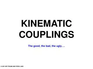
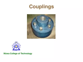
Couplings • Used to connect two shafts together at their ends to transmit torque from one to the other. • Two kinds of couplings: • RIGID • FLEXIBLE
Rigid Couplings NO relative motion between the shafts. Precise alignment of the shafts Bolts in carry torque in shear. N = # of bolts.
Flexible Couplings • Transmit torque smoothly • Permit some axial, radial and angular misalignment
Universal Joints Large shaft misalignments permissible Key factors in selection are Torque, Angular Speed and the Operating Angle Output not uniform wrt input Output IS uniform wrt input
Axial Constraint Methods Spacers Retaining ring Shoulders Retaining ring