Download
1 / 25
250 likes | 372 Views
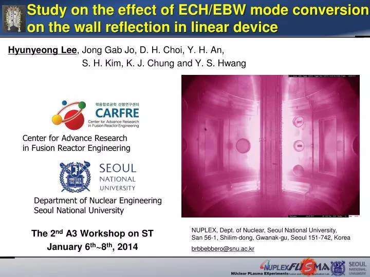
Study on the effect of ECH/EBW mode conversion on the wall reflection in linear device. Hyunyeong Lee , Jong Gab Jo, D. H. Choi , Y. H. An, S. H. Kim, K. J. Chung and Y. S. Hwang. Center for Advance Research in Fusion Reactor Engineering . The 2 nd A3 Workshop on ST

E N D
Study on the effect of ECH/EBW mode conversion on the wall reflection in linear device Hyunyeong Lee, Jong Gab Jo, D. H. Choi, Y. H. An, S. H. Kim, K. J. Chung and Y. S. Hwang Center for Advance Research in Fusion Reactor Engineering The 2ndA3 Workshop on ST January 6th~8th, 2014 Department of Nuclear Engineering Seoul National University NUPLEX, Dept. of Nuclear, Seoul National University, San 56-1, Shilim-dong, Gwanak-gu, Seoul 151-742, Korea brbbebbero@snu.ac.kr
Contents • Introduction • - Motivation and Objectives • - Electron Bernstein Wave(EBW) mode conversion • Experiment Setup • - Experiment setup, Diagnostics • Simulation Result(COMSOL) • - Comparison between the CMA diagram • - The simulation based on diagnosis of the experiment • Experiment Result • - Feasibility of EBW mode conversion • - Density profile along the magnetic field • - HFSX, LFSX and LFSO injection along the wall position • Pre-ionization experiment in VEST • - XB mode conversion in pre-ionization • - Comparison between O&X mode injection • Summary
IntroductionMotivation & Objectives • Electron Cyclotron Heating(ECH) is widely used for various purposesin fusion device that the pre-ionization, local heating and current drive to control the pedestal and the instabilities such as sawtooth, NTM etc. • Especially non-inductive current drive and startup using ECH/CD is essential for Spherical Torus (ST) which has difficulty in start-up due to lack of space for the center stack. • In ST devices which have characteristics of high beta operation and consequent low cutoff density, alternative method using the Electron Bernstein Wave (EBW) which is no cutoff density has been studied. • In most previous works, EBW mode conversion for the wall covered with the chamber hasnot been studied in detail. The investigation of this EBW mode conversion is essential for the fusion plasma research including ST.
IntroductionElectron Bernstein Wave Mode Conversion • Electron Bernstein Wave(EBW) • Electrostatic wave that has no high density cutoff • Electromagnetic wave(ECH) is converted to the electrostatic wave(EBW) only inside the plasma. • Conventional ECH is not suitable to ST due to low cutoff density • - EBW : Attractive for heating and CD in ST • EBW mode conversion coefficient : [1] • Budden parameter : Schematic of the EBW assisted plasma current start-up in MAST[2] Maximum mode conversion efficiency C versus Ln at NSTX[1] [1] Heinrich Peter Laqua, PPCF, 49, R1-R42, 2007 [2] V.F. Shevchenko et.al., Nuclear Fusion, 50, 022004, 2010
Experiment SetupMagnetic Field and Waveguide System Bent Magnetic Field(BT) HFS Injection Bent Magnetic Field(BT) Quartz Tube Pump System Hydrogen Injection Stainless Steel Wall Magnetron LFS Injection MW Loss Protection • Objective • Confirm the effect of ECH & EBW mode conversion • Small cylindrical device with axial magnetic field bent similar to tokamak • Possible to change the direction of microwave(LFS&HFS and O&X mode) • Easily changeable to the magnetic field and MW power • Antenna : open waveguide(WR284) 3 Stub Tuner Quartz Quartz 2.45 GHz Magnetron ` 875G W R 2 8 4 HFS LFS
Experiment Setup Diagnostics – Langmuir Probe Interferometer Radial Probe 2 3 2 4 4 1 3 Axial Probe • Diagnostics – Radial Langmuir probe • Planar type tip(r=1.5mm) • Measured in Z=0cm from the center • Te (linear fit slope of the log scale V-I curve) • ne (the ion saturation current & Te ) • Comparison between Interferometer & Probe • To confirm the density measurement • Assuming that parabolic density profile due to the line integrating density using interferometer • The result shows the similar tendency of the density • In this result the diagnostics was utilized by this probe.
Experiment SetupThe Wall with X/O Polarized Slit Center Hydrogen Injection Pump System Axial Probe Radial Probe O slit wall ∥ parallel 2.45GHz • Objective • Confirm the effect of EBW mode conversion on the wall reflection with polarized slit • The wall is possible to change the position along the injection and opposite side. • X/O slit : The wall with slits that reflects the X/O mode wave • Formation of polarized wave with specific direction to radiate the electric field of wave perpendicular/parallel on the magnetic field • The other wave with different direction will pass through the slit Bt E1 E1┴Bt perpendicular X slit wall
Simulation ResultCMA Diagram – the cutoff from HFS injection HFSO injection HFSX injection : Cutoff(reflection) O cut off X(L) cut off HFS Background Plasma 0 1E16 5E16 3E17 0 1E16 5E16 3E17 Resonance • In case of HFS injection, the O/X(L) cutoff layer exists in CMA diagram. • O mode cutoff density : ~7.5×10¹⁶ #/m3 • X(L) mode cutoff density : ~1.5×10¹⁷ #/m3 • The result of COMSOL simulation also shows the cutoff layer. 1 UHR LFS R(X) cutoff 1
Simulation ResultCMA Diagram – the cutoff from LFS injection LFSO injection LFSX injection : Cutoff(reflection) O cut off X(L) cut off HFS Background Plasma 0 1E16 5E16 3E17 0 1E16 5E16 3E17 Resonance • Also in case of LFS injection, the O/X(R) cutoff layer exists in CMA diagram. • O mode cutoff density : 7.5×10¹⁶ #/m3 • X(L) mode cutoff density : ~1.5×10¹⁷ #/m3 • X(R) mode cutoff density : ~2.5×10¹⁶ #/m3 • The result of COMSOL simulation also shows the cutoff density. 1 UHR LFS R(X) cutoff 1
Experiment ResultThe Feasibility of EBW Mode Conversion : Cutoff(reflection) : XB conversion O cut off X(L) cut off HFS • In HFS case, the injected microwave does not exceed the cutoff density as same as COMSOL result. • In LFSX case, over dense plasma generates which overcomes the cutoff layer. • In LFSO case, the tendency of the density is similar but weak tendency of the LFSX injection. • The feasibility of EBW mode conversion(XB/OXB) has been shown. Resonance 1 UHR LFS R(X) cutoff 1
Experiment Result The Density Profile along the Magnetic Field • The density profile is measured for moving the probe shot by shot. • Due to the limit of the probe size, it was impossible to measure near the quartz wall, so the presumption of the density profile is shown in the dashed line. • Higher plasma density with the low magnetic field not in the ECR, but near the UHR(dashed line) • The density is higher with the lower magnetic field • Broader and higher density in the UHR(steep density gradient due to the narrow chamber) • Feasibility of XB conversion 700W LFSX injection UHR Layer
Simulation ResultThe Feasibility of EBW Mode Conversion LFSO/X injection HFSO/X injection : Cutoff(reflection) : XB conversion O cut off X(L) cut off HFS • The result of COMSOL simulation is conducted with the experiment result(density). • In case of HFS injection, the density from the experiment does not exceed the X(L) cutoff density. • The microwave from LFSO meet the cutoff layer, but LFSX injection overcomes the cutoff layer. • It might be occurred due to the steep density gradient near the UHR. • The feasibility of EBW mode conversion Resonance 1 UHR LFS R(X) cutoff 1
Experiment Result HFSX Injection Opposite Injection HFSX ECR O cut off X(L) cut off HFSX • In case of HFSX injection, the density does not exceed the X(L) cutoff layer. • In all cases of injection side wall, opposite side wall and both wall, the density has the similar tendency – single pass absorption. Resonance 1 UHR R(X) cutoff 1
Experiment Result LFSX Injection – XB Mode Conversion Injection Opposite LFSX ECR O cut off X(L) cut off • In case of LFSX injection • XB mode conversion might be occurred directly. • Steep density gradient near UHR. • The wall positioned in the opposite side of the wave injection affects to the multiple reflection – multi pass absorption. Resonance 1 UHR LFS R(X) cutoff 1
Experiment Result LFSX Injection with Polarized Wall Oslit Xslit LFSX ECR O cut off X(L) cut off • In case of LFSX injection • XB mode conversion and multi pass power absorption due to the wall reflection. • Oslit wall has the similar tendency with the none wall case – no effect of the reflected O wave • Xslit wall – similar to the full wall(XB conversion) Resonance 1 UHR LFS R(X) cutoff 1
Experiment Result LFSO Injection – OXB Mode Conversion Injection Opposite LFSO ECR O cut off X(L) cut off • Opposite side & both wall • The feasibility of OXB mode conversion • OX conversion : O cutoff & wall reflection • Multi pass absorption due to the opposite wall • Injection side & None wall • No overcomes the X(L) cutoff density • Further research is required to understand the wave movement after MW meets the O cutoff layer. Resonance 1 UHR LFS R(X) cutoff 1
Experiment Result LFSO Injection with Polarized Slit Oslit Xslit LFSO ECR O cut off X(L) cut off • In case of LFSO injection • Xslit & Full wall • The feasibility of OXB mode conversion • the similar density tendency • Oslit & None wall • No existence of the reflected X wave • XB conversion does not occurs. Resonance 1 UHR LFS R(X) cutoff 1
Pre-ionization experiment in VESTXB Mode Conversion in Pre-ionization LFSX Injection UHR R cutoff • Based on the linear device experiment, the pre-ionization experiment in VEST is conducted with only TF field. • Initial breakdown occurs in ECR with low ECH power, and then UHR moves outward increasing ECH power that means the electron density buildup. • The density profile in VEST shows that the electron density peak exists near the UHR which has the steep density gradient and it means the feasibility of XB mode conversion.
Pre-ionization experiment in VESTComparison Between O & X Mode Injection O-mode X-mode Only X-mode • The density and temperature of LFS O mode injection is similar to LFS X. • Reflected MW diagnostics shows OX and no XO mode conversion.
Summary • To confirm the effect of ECH and EBW mode conversion on the wall reflection, the experiment is prepared. • With the simulation named as COMSOL based on the experiment result, the feasibility of EBW mode conversion near the steep density gradient is found. • In LFS injection, the feasibility of XB & OXB mode conversion is confirmed and higher plasma density with the low magnetic field not in the ECR, but near the UHR as same as the simulation result. • In case of LFSX injection, XB mode conversion is occurred directly due to the steep density gradient and multi pass power absorption with opposite side wall and in case of LFSO, OXB mode conversion may occur in the UHR and O cutoff layer. • The pre-ionization experiment in VEST is conducted and the result also shows the feasibility of XB and OXB mode conversion near the UHR.
Preliminary ECH Experiment Result(3) • X_Slit/O_Slit : The wall with X/O mode MW radiation when reflection is occurred in the wall • Density : Wall > X_Slit > O_Slit > No_Wall • Over dense plasma and X mode polarized wave effect shows the evidence of the EBW mode conversion(XB) • The result of monitoring the leakage MW • No_wall > O_Slit > X_slit LFSX injection Leakage MW power monitoring
Coil Geometry 1.5 1 0.5 Future Work Z (m) 0 -0.5 -1 -1.5 0 0.2 0.4 0.6 0.8 1 R (m) • 7.9GHz MW source installation • Inboard startup using trapped particle configuration – the peak density of the pre-ionization plasma near the inboard side. • Study for the ECH harmonic efficiency • EBW mode conversion experiment • Closed flux surface formation in trapped particle configuration – the possibility of the steep density gradient to make EBW mode conversion • In conventional startup, the steep density gradient will be made using local limiter in front of the waveguide launcher • Non-inductive current drive experiment • In steady state plasma, the possibility of the ECCD/EBCD will be investigated. 2.45GHz FHM 7.5GHz THM 7.5GHz FHM O-mode cutoff 7.5GHz SHM 2.45GHz UHR Various EC Resonance Layer in VEST
LFSX injection LFSO injection Experiment Setup LFSX injection LFSX 5e16 5e16 1e16 1e16