Download
1 / 22
220 likes | 569 Views
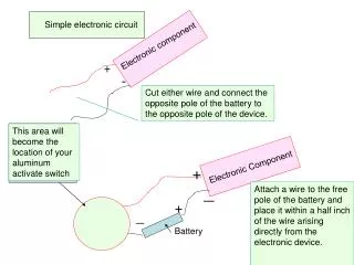
APPLIED ELECTRONIC CIRCUIT. 김서주 김혜리 유예림 차온유 홍주영. APPLIED ELECTRONIC CIRCUIT. 증 폭 기 ( Amplifier ). AMP. IN-PUT. OUT-PUT. 전원에서 에너지를 공급하면 입력신호의 에너지를 증가시켜 출력 측에 큰 에너지의 변화로 출력하는 장치. POWER SUPPLY. APPLIED ELECTRONIC CIRCUIT. 전압 증폭기 (Voltage Amplifier ).

E N D
APPLIED ELECTRONIC CIRCUIT 김서주 김혜리 유예림 차온유 홍주영
APPLIED ELECTRONIC CIRCUIT 증 폭 기(Amplifier) AMP IN-PUT OUT-PUT 전원에서 에너지를 공급하면 입력신호의 에너지를 증가시켜 출력 측에 큰 에너지의 변화로 출력하는 장치 POWER SUPPLY
APPLIED ELECTRONIC CIRCUIT 전압 증폭기(Voltage Amplifier)
APPLIED ELECTRONIC CIRCUIT 전류 증폭기(Current Amplifier)
APPLIED ELECTRONIC CIRCUIT Trans-resistance Amp
APPLIED ELECTRONIC CIRCUIT Trans-conductor Amp
APPLIED ELECTRONIC CIRCUIT Basic amplifiers and their ideal terminal resistances
APPLIED ELECTRONIC CIRCUIT 부하 효과(Loading effect) voltage divider의 출력 전압이 고정 되지 않지만 부하에 따라 달라진다. 비교적 안정된 출력 전압을 구하는 출력 전류는 입력 전류의 작은 부분 이여야 한다. 부하효과의 결점은 대부분의 입력된 전류는 divider에서 열로 낭비된다는 것이다.따라서 이에 대한 대안으로voltage regulator를 사용하면 부하효과를 줄일 수 있다. * 전압원에게 부하 = 부하저항에 흘려줘야 하는 전류 부하저항이 작아질수록 전류를 더 많이 공급해야 한다(부하) * 전류원에게 부하 = 출력 전압
APPLIED ELECTRONIC CIRCUIT 연산 증폭기(Operational amplifier) Operational Amplifier의 줄임말로 연산증폭기를 의미한다. 차동 증폭기로서 역할을 하며 두 단자의 전압을 뺄셈하여 증폭해 주는 역할을 하는 소자이다. 따라서 작은 전압을 큰 전압으로 증폭해 주는 용도로 많이 사용한다.
APPLIED ELECTRONIC CIRCUIT Ideal-op amp & Practical-op amp (=Loading effect가 작아짐 at input) (=Loading effect가 작아짐 at output) (=open)
APPLIED ELECTRONIC CIRCUIT In-put mode of Op-Amp * Single-ended mode : 한쪽은 그라운드, 한쪽은 신호로 연결. 증폭된 신호가 출력된다. * Differential input mode : 위상이 반대인 입력신호를 두 인풋에 모두 연결. 인풋 차이를 증폭한 값이 아웃풋이다. * Common mode : 동일 위상, 주파수, 진폭의 입력을 가한다. 이상적으로는 출력은 0V이다. 즉 두 입력 단에 만약에 불필요한 공통적인 노이즈가 있으면 common mode rejection에 의해 노이즈가 제거된다.
APPLIED ELECTRONIC CIRCUIT (Differential) (Differential) (Common)
APPLIED ELECTRONIC CIRCUIT * single-ended / differential * single-ended / single-ended OP-AMP * differential / differential * differential / single-ended
APPLIED ELECTRONIC CIRCUIT 비반전 증폭기(Non-inverting Amplifier) * 입력된 신호에 대해 정해진 증폭도로 신호가 비반전되어출력되는 증폭기 * 음전압 = 양전압, 입력 전류 = 0
APPLIED ELECTRONIC CIRCUIT * Negative Feedback을 가지는 선형 Op-Amp 회로의 해석 이득의 안정화 선형성 중간에 들어온 잡음을 줄여줌
APPLIED ELECTRONIC CIRCUIT Negative Feedback (=degenerative)
APPLIED ELECTRONIC CIRCUIT 반전 증폭기(Inverting Amplifier) * 입력된 신호에 대해 정해진 증폭도로 신호가 반전되어 출력되는 증폭기 * 음전압 > 양전압, 양전압 > 음전압(신호의 모양은 유지하면서 증폭)
APPLIED ELECTRONIC CIRCUIT 가상 접지(virtual-ground) * 과 사이의 전압은 0으로 전압이 같다. : 열린 이득 G=∞ * 에 들어가는 전류는 0이다. 입력 임피던스 Rin=∞ 이득이 줄어들기 때문에 Loading effect 발생!
CANONNAM POWERPOINT? Non-inverting Amplifier & Inverting Amplifier
CANONNAM POWERPOINT? Voltage buffer (=unity gain buffer) 이상적 증폭률 1인 비반전증폭기 완충 증폭기로서 입,출력 임피던스가 다른 두 개의 회로를 연결할 때 사용
CANONNAM POWERPOINT? 테브닌 등가회로 예시 신호원 신호원 저항 없음