Download

1 / 29
290 likes | 325 Views
Explore innovative propellant formulations and geometric configurations to enhance ballistic performance. Learn the crucial considerations and test methodologies for high-density propellants in fast-core applications.

E N D
Mechanical Properties Considerations for Fast Core Propellants Pam Kaste Michael Leadore Joyce Newberry Robert Lieb 39th Annual Guns and Ammunition Meeting Baltimore, MD 16 April 2004
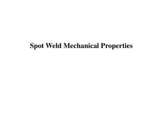
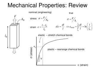
Burn Rate Ratio: > 2.5 : 1 Projectile exits gun chamber Slow BurningOuter Layer Pmax Fast BurningInnerLayer Time (distance) Layered Propellants for Improved Ballistic Performance Chemical progressivity: distinct propellant formulations - Avoid plasticizers to prevent migration & recrystallization problems Novel colayered geometries High loading densities > 1.25 g/cc
Fast-Core Enabling Technologies are Revolutionary and Impose Tough Constraints on the Propellant Very High Energy Density High Energy Propellant High Loading Density Propellant ~1.3 gm/cc vs ~ 0.95 gm/cc Vertical Disk Configuration Important limitations on ignition & flamespread Schematic
Fast-Core Imposes Tough Constraints on the Propellant Electrothermal Chemical Ignition Needed as an Enabler for High Loading Density Charges Plasma could cause unpredictable behavior with thin layers/coatings Breech Pressure, (as opposed to Gun Pmax) May Limit Performance More Stringent Low Temperatures Being Considered Conventional operating T range: ~ -20 C to 63 C Future ranges: -32 C to 63 C
Schematic of Servohydrualic Test Apparatus Dynamic Compression Testing Screens for Brittle Failure
Servohydraulic Test Apparatus Specimen strain ~100 s-1 L/D ~ 1- 1.2 Diameter ~ 1 cm (although 0.25 inch samples have been evaluated successfully) Sample is a Single Specimen
Ridge Inner Layer Outer Layer Dimensions of Some 120-mm Cartridge Propellants 120-mmLength Width Aspect Ratio Cartridge Propellant cm cm L/W JA2 19 Perf Hexagonal 1.62 1.51 1.07 JA2 7 Perf Cylindrical 1.63 1.07 1.6 M14 7 Perf Cylindrical 1.08 0.54 2.0 Co-layered Propellants Width ~ 5-10x less Aspect ratio can be huge
JA2 Reference Sample A Sample B Solid Strand Propellant Candidates Cylinders of L/D ~ 1 The geometries of cylinders cut from strands (L/D~ 1) are amenable to SHT!
Sample A Cylinder Relative Units of Stress (MPa) JA2 Grain Strain (%) Servohydraulic Test Results -32 C Both of these samples maintain strength after maximum stress !
Sample B Cylinder Relative Units of Stress (MPa) JA2 Grain Strain (%) Servohydraulic Test Results -32 C Both of these samples maintain strength after maximum stress !
Ridge Inner Layer Outer Layer - How to Test Sheet and Co-Layered Samples ? No Bonding 4 Colayered Units Stacked Height ~ 1 cm Units Not Bonded Together Single Co-Layered Propellant Unit Bonds Well During Processing
JA2 Grain Relative Units of Stress (MPa) Strain (%) Servohydraulic Test Results -32 C ABA Colayered Sample Non-Bonded, Stacked Disks Stacked Samples vs Grains
What would happen if Loose Stacks, Cut from Sheet JA2, were tested in the SHT ?
Servohydraulic Test Results Sheet JA2, -32 C Non-Bonded JA2 Samples 3.2 mm 1.8 mm 1.3 mm (Original Thickness in mm) Relative Units of Stress (MPa) Single Structure JA2 Strain (%)
1.3 mm 1.8 mm 3.2 mm Fracture at -32C Post-SHT Archaeology Loosely Stacked, Multi-Structure Layers JA2
Servohydraulic Test Results -32 C Stacks, Cut from Sheet JA2 Securely Bonded with Minimal Adhesive
JA2 Grain Stress (MPa) JA2 Adhesively-Bonded Layers Strain (%) Servohydraulic Test Results -32 C
Servohydraulic Test Results -32 C ETPE Samples A and B Loose Stacks vs Stacks Securely Bonded with Minimal Adhesive
Non-Bonded Propellant Stacks Sample A Sample B Before (Sample A) After Sample A Sheet No Adhesive Bonding
Sample A Sample B ETPE Samples Prepared for SHT Analysis -32 C Adhesively Bonded Samples Adhesively stacked samples can barely be cut apart with a razor.
Servohydraulic Test Results Stacks of Sample A, -32 C Adhesively Bonded Relative Units of Stress (MPa) More Negative Failure Modulus Non-Bonded Strain (%)
Adhesively Bonded Relative Units of Stress (MPa) Non-Bonded More Negative Failure Modulus Strain (%) Servohydraulic Test Results Stacks of Sample B, -32 C
How do the SHT results of Adhesively Bonded ETPE Disks compare with those of Cylinders?
Servohydraulic Test Results -32 C Sample B Cylinders Bonded Disks Stress (MPa) Strain (%)
Bonded Disks Relative Units of Stress (MPa) Cylinders Strain (%) Servohydraulic Test Results -32 C Sample A
Summary of SHT Analysis Stacked sheet specimens have not been validated as a measure of propellant response Current correlations between ballistic fracture generation and mechanical response are dependant upon monolithic specimens - Stacked layers of JA2 exhibit significantly greater fracture generation Stacked layers show a response more similar to a monolithic structure when: - Samples that are adhesively bonded - Samples that are compressed sufficiently prior to evaluation so that the individual layers do not slip, and all layers can help support a load The potential exists for creating artifacts when making a layered material approach a monolithic form
Why has SHT Screening of Granular Propellants been so Effective? Propellant Grain Anvil www.ditusa.com/bomb.html Stress Strain Acceptable Unacceptable SHT Compressive Failure was correlated to propellant response under gun conditions. Simulated Gun Conditions Gas gun impact tester was used to fire cylindrical grains of propellant with known burning rate face-on at an anvil at velocities known to occur near ignition areas in large caliber guns firings. Propellant Shards Collected Quantitatively Shards are fired in a closed bomb, and surface area of shard computed SHT Analysis
Mechanical Properties Assessment of Colayered Propellant What is needed for colayered propellant configurations: - To design a test to characterize the mechanical response under operational conditions - Operational conditions, i.e. the environment to which a typical large caliber layered charge is exposed, must be determined via ballistic modeling and simulation - Mechanical response is not solely a function of the mechanical properties of the propellant - For all propellants, form is important - For colayered propellants, form may be a dominant factor