Download

1 / 41
470 likes | 835 Views
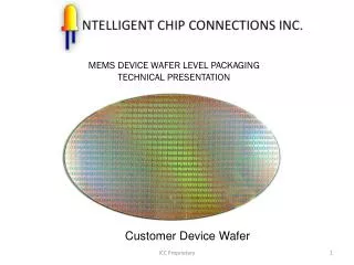
Transforming Flip Chip. Back Into a CSP. with Reworkable Wafer-Level Underfill. Ken Gilleo - ET-Trends David Blumel Alpha Metals. Ken@ET-Trends.com. Outline. The Packaging Revolution Flip Chip vs. CSP Why Underfill? Classes of Underfill Final Generation FC; a CSP Conclusions.

E N D
Transforming Flip Chip Back Into a CSP with Reworkable Wafer-Level Underfill Ken Gilleo - ET-Trends David Blumel Alpha Metals Ken@ET-Trends.com
Outline • The Packaging Revolution • Flip Chip vs. CSP • Why Underfill? • Classes of Underfill • Final Generation FC; a CSP • Conclusions
PACKAGING REVOLUTION ?
Driven by: smaller faster cheaper (thriftier)
The Package Design Portability Power Is the KEY to achieving: Cost Reduction Performance Convergence Simplicity
MARKET DEMANDS Printed Circuits Driving Forces Semi- Conductors Packaging
Smaller Faster = more leads PROBLEM The whose time already came! “Can’t be solved by packaging evolution”
Area Array Solution n2 > 4n-4
The Entire Packaging History BGA 1960's Hot for the 21st Century FC-BGA Flip Chip (C4) Flip Chip (re-Engineered) Chip-on-Board Lead Frame TBGA SMT TCP (TAB) Spider Feed-thru m BGA CSP/FC-BGA Flip Chip Strip SMT micro-SMT Beam Lead Chip
3 2 ULTIMATE 1 IC SMT DCA COB & TAB Packaging Trends • Perimeter Leads Area Array • Size: chip scale • Packaging: minimal • Packaging: post- and concurrent • Paths/lead length: shorter
What is a PACKAGE? Is Flip Chip a True PACKAGE?
Translation: IC to PCB PACKAGE the Removability Environmental Protection Standardization
FLIP CHIP 360o REVOLUTION 2nd Generation 1963 1990’s CSP Package? Low Cost 1st Generation New bumps, organic substrate + 1964 Underfill Final Generation High Cost High lead, ceramic substrate CSP again
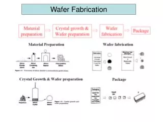
Flip Chip Components • Under Bump Metallization • Bumps & bumping • Joining materials & agents • Assembly processes • Underfill
Bumping Methods • Attach discrete spheres;Au, Cu, Sn/Pb • Print joining mat's;Sn/Pb or Conductive Adhesive • Vacuum deposit metal:old, still alive • Electrolytic plating;Au, Cu, Sn/Pb, Ni (cost issue?) • Electroless plating;Au, Cu, Ni (NEWER) • Fluid jet molten metal;Sn/Pb (VERY NEW) • Stud bump with;Sn/Pb, CU or Au(single chip) • Material transfer;Sn/Pb or Cond. Adhes.; paste or film metal vapor
The 2nd Generation FC Problem • Switch to organic substrate • Causes large thermal mismatch • Low reliability in thermocycle • Mismatch must be addressed • low CTE organic substrate • columns instead of bumps • non-fatiguing joints??? • mechanical coupling: chip-to-substrate
Thermal Mismatch Kills Reliability H e a t i n g C o o l i n g CHIP Sn/Pb
UNDERFILL Mechanism Y Y p p o o s s i i t t constrained i i o o n n
GET Underfill: What You • A real aggravation • Added equipment • Added floor space • Added cost • Reduced yield
WANT Underfill: What You • Self-Dispensing • Self-Fluxing • No added equipment • No added time required • Cost-effective • Reworkable "Transparent" to the Assembly Process
Underfill Events • “Underfill Effect” discovered: 1960’s • Slow flow, slow cure the norm: early 1990’s • Fast flow(>2.5cm/min.),30 min. cure: 1995 • Pre-dispense flux-fill R&D: mid-1990’s • Snap flow(>3 cm/min) /Snap cure (5 min.): 1997 • Convert FC to SMT: 1998 - 1999 • Wafer-level: coming in 1999 - 2000
Types of Underfill APPLIED to PHASE Pre- Dispensed Post- Dispensed SUBSTRATE Liquid Available NA Solid Available NA Chip/Wafer Liquid NA ? Solid R & D NA Chip & Substrate Concurrently Liquid Available Available Solid NA NA
Capillary Type(post dispensed) • Flow rate is close to max. • Cure time is close to min. • Still adds • equipment • space • time • cost • Result: FC = SMT
PRODUCTIVITY Plateau
Pre-Dispensed Liquid • Process control is critical • Requires dispenser/printer • Solder reflow oven provides cure • Enables FC = SMT • Result: next generation underfill
Pre-Dispensed Flux/Underfill Not Assembled Post-Dispensed Underfill Pre-Assembled
Pre-Dispense Solid on Substrate • Film-on-PCB • Special, expensive equipment • Not an SMT process • Doesn’t address underfill problems An old concept?
Anisotropic Conductive Adhesive ACA film has a built-in underfill and is the 1st example of pre-dispensed solid underfill.
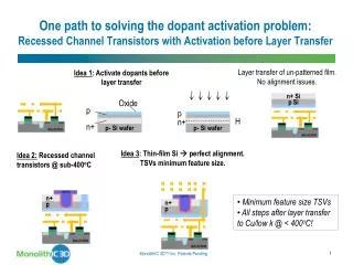
Pre-Dispense Solid on Chip • Wafer-level applied • Self-fluxing • Dry solid • Integral to Flip Chip • True SMT process • Transparent to assembler • Can be reworkable
Integrated Flux-Underfill Liquid polymer-based composition is coated onto Flip Chips at wafer-level and then converted to a SOLID that:(1) Permits a bumped wafer to be diced into Flip Chips.(2) Provides flux for assembly.(3) Liquefies to a thermoplastic underfill during reflow.(4) Polymerizes and wets substrate during reflow step . (5) Remains reworkable after reflow stage cure.
Ramifications: • FC becomes a std. SMT process. • FC becomes CSP if reworkable. • Underfill becomes a semiconductor process. • The ready-to-bond FC becomes the most cost-effective minimal package. • Success can make this package the dominant micropackage.
Assembly Process • Pick & Place FC from any format • Reflow • flux melts/activates • underfill liquefies/wets • solder melts/forms joint • underfill solidifies • Test • Rework if required
Assembly Process Solder joints form, underfill properties generated TEMP Melts; flux activates, begins to bond to substrate Flux has deactivated, material is now an underfill TIME in Solder Reflow Oven
Issues & Challenges • Materials; single or multiple? • Shelf life, what is required? • What wafer Coating process? • Dicing with polymer in place? • Assembly • voiding, filleting, adhesion • process sensitivity
FLIP CHIP Solid Flux FLIP CHIP INTEGRTATED/FLUXFILL Type 1 - Single material converts from flux to underfill during reflow
FLIP CHIP INTEGTRATED FLUX/UNDERFILL FLIP CHIP Solid Thermoplastic Underfill Solid Flux Type 2 - Two separate materials Many variations
Status Technology 2-LAYER 1-LAYER MATERIALS complete being optimized WAFER COATING being optimized selection stage DICING Feasibility confirmed to be determined FC ASSEMBLY confirmed to be determined RELIABILITY to be determined to be determined
Phase 1 Test Platform Transparent 12 mm x 12 mm Flip Chip Bonded to Copper with single-layer Flux/Underfill by running through an IR reflow oven at 220oC Copper sheet Purchased quartz FC with Sn/Pb bumps Flux/underfill after heating Delco is not a sponsor or participant
Conclusions • Today’s underfills impede FC • FC = SMT: required for max. success • Underfill can be a semicon process • FC will become a CSP again • Result: best micropackage solution
Everything should be made as simple as possible but not simpler. Albert Einstein The Ultimate Micro Package Just add heat; some assembly required.