Download
1 / 16
190 likes | 427 Views
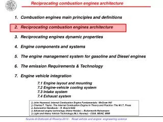
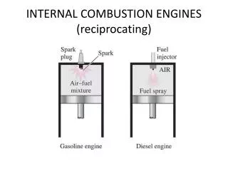
Combustion engines main principles and definitions Reciprocating combustion engines architecture Reciprocating engines dynamic properties Engine components and systems The engine management system for gasoline and Diesel engines The emission Requirements & Technology

E N D
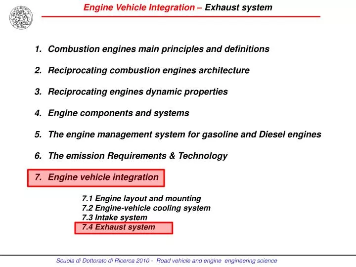
Combustionenginesmainprinciples and definitions Reciprocating combustionengines architecture Reciprocating engines dynamic properties Engine components and systems The engine management system for gasoline and Diesel engines The emission Requirements & Technology Engine vehicle integration 7.1 Engine layout and mounting 7.2 Engine-vehicle cooling system 7.3 Intake system 7.4 Exhaust system
HOT END • Exhaust manifold and turbo group Performance • Catalysts and Particulate Filter Emission COLD END • Mufflers (silencers) • Volume & technology Comfort
Design guidelines for gasoline engines • Exhaust manifold designed to optimize engine torque and/or power: for example, duct diameter and length, and for 4 L, the distance of the firs junction (1-3, 2-4) and also of the second from the cylinder head. • Adequate catalyst volume (space velocity): roughly equivalent to the engine capacity. • Optimization of the catalyst canning inlet flow to address the entire catalyst surface. • Reduced thermal inertia of the exhaust system upstream the catalyst for a faster catalyst warm-up
Short and simple exhaust manifold (4-1) Example of catalyst positioned very close to the engine (close coupled) inside the engine compartment
Catalyst positioned very close to the engine (close coupled) inside the engine compartment
Twin main catalyst positioned inside the engine compartment of a high performance 4 L engine
Twin main catalyst positioned inside the engine compartment of a high performance 4 L engine (bottom view)
Complete exhaust system Two pre-catalysts inside the engine compartment and under-floor main (4L engine)
L6 engine longitudinal installed – Twin exhaust system (one for each cylinder head): two close-coupled pre-catalysts and two under floor main catalysts
L6 engine longitudinal installed – Twin exhaust system (one for each cylinder head): two close-coupled pre-catalysts and two under floor main catalysts (bottom view)
V6 engine transversal installed – Twin exhaust system (stereo system): two close-coupled pre-catalysts and two under floor main catalysts
Design guidelines for Diesel engines • Manifold design to optimize the inlet flow to the turbo and to reduce the local thermal stress. • Adequate catalyst and particulate filter volumes: 0.8-1.0 engine capacity • Catalyst and particulate filter positioned as close as possible downstream the turbo outlet.
Catalyst positioned immediately downstream the turbo of a direct injection Diesel engine
Catalyst positioned downstream the turbo of a direct injection Diesel engine
Catalyst positioned downstream the turbo of a direct injection Diesel small capacity engine