Download
1 / 31
981 likes | 2.19k Views
ENGINEERING DRAWING. What is Engineering Drawing..? It communicates an idea, design, schematic or model. It comes in many forms- Electrical -Civil - Mechanical. What is the need…..?. That’s why Drawing is the L anguage of Mechanical Engineers….!!. What is Projection…?.

E N D
ENGINEERING DRAWING • What is Engineering Drawing..? • It communicates an idea, design, schematic or model. • It comes in many forms- Electrical -Civil -Mechanical
That’s why Drawing is the Language of Mechanical Engineers….!!
What is Projection…? ISOMETRIC PROJECTION ORTHOGRAPHIC PROJECTION
METHODS OF PROJECTIONS: • FIRST ANGLE METHOD OF PROJECTION: • THIRD ANGLE METHOD OF PROJECTION:
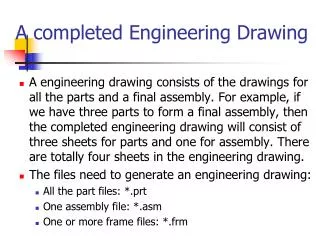
MACHINE DRAWING • It contains: • Drawing of machine components, machine assemblies and subassemblies. • Conventional representation of different materials, sections and machine components. • Representations of limits, fits & tolerances etc. • Modeling softwares.
ASSEMBLY DRAWING: • Assembly is combination of various links & parts grouped together to perform some function. • It’s the drawing which shows various parts of machine in their working position. • One can find the way & sequence in which these parts are assembled together.
ASSEMBLY DRAWING (contd…) • Assembly drawing should satisfy: • Manufacturing requirements, • Operational requirements, • Maintenance requirements.
DETAIL DRAWING: • Describes a single part, or several parts individually with all detail specifications. • For manufacturing individual parts we need detailed drawing of each part. • It should furnish complete information & standard conventions. • These are made from the assembly drawings.
DETAIL DRAWING (contd…) • It should carry : • Size & shape description with min. possible no. of orthographic views. • Special sections/auxiliary/pictorial views. • Thorough dimensions. • Material, surface finish grade, No. of parts required, etc.
Identification • Ballooning: - A part is located and identified, in an assembly drawing, by using a circle containing the part number and a leader line that points to the corresponding part.
Leader lines point to the corresponding part. Balloons containing part numbers.
The leader lines; • should not cross, • be as parallel as possible.
Parts List / Bill of Material • The parts list is an itemized list of the parts that make up the assembled machine.
Parts List / Bill of Material • Parts lists contains: • Part number, part name, the number required and the material of the part. • Parts are listed in order of their part. • Parts are usually assigned based on the size or importance of the part.
The parts list may be placed in the upper right corner of the drawing. - Part# 1 is at the top.
The parts list may be placed in the lower right corner of the drawing. - Part# 1 is at the bottom.
NEED OF SOFTWARES : • Increases accuracy & productivity of designer. • Allows design alterations. • Transfer of drawing is faster & cheaper. • Easy to store & retrieve. • Better drawing visualization through colours. • Improves the quality of drawing.
SOFTWARES • AUTO CAD (Computer Aided Drafting) • CATIA • PRO-E • SOLIDWORKS