Download
1 / 12
130 likes | 222 Views
Conceptual Design for HYLIFE-II Maintenance. Ryan P. Abbott ARIES Project Meeting May 6, 2003. This work was performed under the auspices of the U.S. Department of Energy by the University of California, Lawrence Livermore National Laboratory under contract No. W-7405-ENG-48. Overview.

E N D
Conceptual Design for HYLIFE-II Maintenance Ryan P. Abbott ARIES Project Meeting May 6, 2003 This work was performed under the auspices of the U.S. Department of Energy by the University of California, Lawrence Livermore National Laboratory under contract No. W-7405-ENG-48
Overview • Motivations for periodic maintenance capability • Introduction to HYLIFE-II parametric CAD model • Details of maintenance capability • Future work • Questions and Feedback
History of Periodic Maintenance Issue • Many threats will assault HYLIFE-II chamber components • Radiation • He embrittlement • Volumetric swelling • Activation • Dynamic • Erosion • Pulsed thermal stresses and fatigue • Material performance uncertainties prompt an investigation into the economic tradeoffs of periodic chamber maintenance • Various material damage limits considered • Flibe pumping power and plant downtime accounted for • COE normalized to 100 dpa limit and no maintenance for 30 fpy
History of Periodic Maintenance Issue • Results of investigation presented at October 2002 ARIES meeting • LLNL starts parametric CAD model of HYLIFE-II chamber • Serve as a flexible platform for integrating previous concepts with future changes and innovations • Stimulate greater interaction between groups within HIF community • Design decided to be updated to support periodic maintenance • Be compatible with basic remote handling equipment • Make all components down to first-wall removable
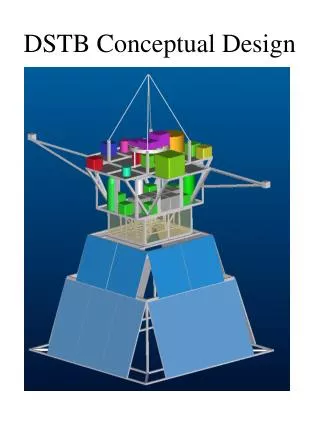
HYLIFE-II Parametric CAD Model - Introduction • Previous graphical design work • Restricted to 2-D • Updates time consuming • Difficult visualization for uninitiated • No interference checking • Current model • Fully 3-D solid • Rapid design changes • Components export directly to finite element analysis routines • Subsystems easy to isolate • Animation and rendering capability
HYLIFE-II Parametric CAD Model - Pictures “BOOM!” – John Madden
HYLIFE-II Maintenance Concept - Introduction • Broad features • Depends only on vertical cranes and simple robotic manipulators • Does not compromise any functional capability of previous chamber • Most internal components assembled as a single modular unit to be replaced in entirety • All structures down to first-wall easily accessible
HYLIFE-II Maintenance Concept - Animation • Procedure details • Remove chamber top • Pull beamline assembly • Extract main drive shafts • Lift out pocket nozzle assembly • Pull cross jet nozzles • Remove cross jet supports • Service first-wall • Reinstall new components in reverse order Double-click on picture to play animation
Future Work on HYLIFE-II Model • Beamline region • Add vortex shielding systems • Beam neutralizers • Target injection apparatus • Main chamber • Cross-jet flow redirectors • First-wall detail • First-wall removal procedure • Rest of plant • Integrate chamber model with other plant systems