Download
1 / 35
350 likes | 501 Views
Beam Induced Pressure Rise in RHIC. Wolfram Fischer Thanks to M. Blaskiewicz. P. He, H.C. Hseuh, H. Huang, U. Iriso-Ariz, L. Smart, S.Y. Zhang 13 th ICFA Beam Dynamics Mini-Workshop on “Beam Induced Pressure Rise in Rings” 9 December 2003. Abstract. Beam Induced Pressure Rise in RHIC

E N D
Beam Induced Pressure Rise in RHIC Wolfram Fischer Thanks toM. Blaskiewicz. P. He, H.C. Hseuh, H. Huang, U. Iriso-Ariz, L. Smart, S.Y. Zhang 13th ICFA Beam Dynamics Mini-Workshop on“Beam Induced Pressure Rise in Rings”9 December 2003
Abstract Beam Induced Pressure Rise in RHIC When filling RHIC with intense ion beams, pressure rises are observed that are high enough to cause experimental backgrounds or even prevent machine operation. Currently this is one of the most severe limitations in the quest for higher luminosity. Pressure rises were observed with all ion species in RHIC: gold, protons and deuterons. While electron clouds were clearly established as a source of beam induced pressure rises, the role beam loss induced desorption is still under investigation. We summarize the observations, the effect of corrective actions taken, and plans for further improvements.
Contents • Introduction • Vacuum test equipment • Observations • Injection • Transition • Counter measures • Solenoids • NEG coated pipes • Bunch patterns • Scrubbing • Summary
Introduction – RHIC accelerator complex 2 superconducting rings 3.8 km circumference~600m warm per ring
Introduction – RHIC challenges • Four experiments (2 large, 2 small), different preferences • More flexibility than at other hadron colliders • Variation in particle species, also asymmetric So far Au+Au, d+Au, p+p, others possible • Variation in energy Au+Au at 10, 66, 100 GeV/u p+p at 100 GeV (250 GeV planned in year after next) • Variation in lattice Low b* in most cases (1-3 m) Large b* for small angle scattering experiments (>10 m) Polarity change in large experimental magnet about every 2 weeks • Short runs (~30 wks/year), often with multiple modes • Significant amount of set-up time required • Difficult to achieve large integrated luminosity Further luminosity limitations hinder experimental programs (heavy ions and polarized protons)
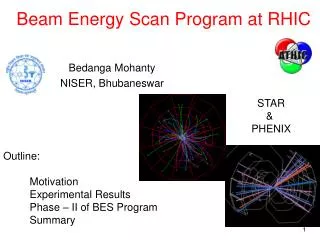
Introduction – detector events Au+Au collision seen by the STAR detector a few thousand tracks along beam direction sideways
Introduction – RHIC physics results • d+Au similar to p+p • Au+Au is different: High pT particles are suppressed in collisions • Au+Au forms opaquestate of matter that hasnot existedsince shortlyafter the Big Bang(~13 billion years ago) [not yet called QGP, quark-gluon plasma] Mini video by Jeffrey Mitchell, PHENIX
Vacuum test equipment (1) • Pressure gauges • Residual gas analyzers • 16 electron detectors • 11 RHIC e-detectors • 4 SNS e-detectors • 1 ANL e-detector • 1 Micro-channel plate • 64m of solenoids • Maximum field: 6.8 mT [68 G] • 60m of NEG coated pipes
Vacuum test equipment (2) Loralie Smart IR10
Pressure rise observations 1st fill with 110 Au79+ bunches N=0.50·109 Oct. 2001 Beam lossesduring acceleration next fill N=0.44·109 10-7 Torr abort limit
Pressure rise mechanisms Pressure rise mechanisms considered so far • Electron cloud confirmed, see later • Coherent tune shift in bunch train • Electron detectors • Ion desorption ruled out • Rest gas ionization, acceleration through beam • Ion energies ~10eV • Effect too small to explain pressure rise at injection • Beam loss induced desorption unclear, see later • No reliable desorption coefficients • Need to have beam losses in all locations with pressure rise [W. Fischer et al., “Vacuum pressure rise with intense ion beams in RHIC”, EPAC’02]
Electron cloud observation at injection (1) Indirect observation – coherent tune shift along bunch train 33·1011 p+ total, 0.3·1011 p+/bunch, 110 bunches, 108 ns spacing (2002) (1) From measured tuneshift, the e-cloud density is estimated to be 0.2 – 2.0 nC·m-1 (2) E-cloud density can bereproduced in simulationwith slightly higher chargeand 110 bunches (CSEC by M. Blaskiewicz) DQ2.5·10-3 [W. Fischer, J.M. Brennan, M. Blaskiewicz, and T. Satogata, “Electron cloud measurements andobservations for the Brookhaven Relativistic Heavy Ion Collider”, PRSTAB 124401 (2002).]
Electron cloud observation at injection (2) Direct observation – electron detectors U. Iriso-Ariz Observation: 88·1011 p+ total 0.8·1011 p+/bunch 110 bunches 108 ns spacing Simulation: Variation of SEYmax: 1.7 to 2.1 Keep R=0.6 (reflectivity for zero energy) Good fit for SEYmax = 1.8 and R=0.6 Code: CSEC by M. Blaskiewicz bunches with lower intensity [U. Iriso-Ariz et al. “Electron cloud and pressure rise simulations for RHIC”, PAC’03.]
Electron cloud observation at injection (3) Electron cloud and pressure rise U. Iriso-Ariz 86·1011 p+ total, 0.78·1011 p+/bunch, 110 bunches, 108 ns spacing e-cloud and pressure Clear connectionbetween e-cloudand pressure atinjection Estimate for heassuming pressurecaused by e-cloud: 0.001-0.02 (large error from multiple sources) 12 min total beam intensity [U. Iriso-Ariz et al. “Electron cloud observations at RHIC during FY2003”, in preparation.]
Total intensity Pressure H2 CO H2O Gas composition at injection Gas composition in IR12 during pressure rise P. He
Transition observation (1) Pressure rise at transition (causes experimental background)Transition:- short bunches (4ns vs. 18ns at injection, enhanced e-cloud)- large momentum spread (possibly momentum scraping) [S.Y. Zhang et al., “RHIC pressure rise and electron cloud”, PAC’03 (2003)]
Transition observation (2) S.Y. Zhang [max] Total charge of both beams [79109e] [S.Y. Zhang, “Experiment Background in RHIC Deuteron-Gold Run”, BNL C-A/AP/107 (2003)]
Transition observation (3) Transition pressure rise not dependent on bunch spacing S.Y. Zhang [max] 110 bunches55 bunches Total charge of both beams [79109e]
Transition observation (4) Only 1 direct e-cloud observation at transition,in conjunction with total beam loss U. Iriso-Ariz 82·109 Au79+ total, 0.75·109 Au79+/bunch, 110 bunches, 108 ns spacing e-cloud signal Only Au beam accelerated, allbeam lost attransition 1 turn bunch pattern
Counter measures • In-situ baking (>95% of 700m/ring warm pipes baked) Occasionally installation schedules too tight • Solenoids (only against e-clouds) Tested last year • NEG coated pipes Installed last shut-down • Bunch patterns (only against e-clouds) Tested last year Implemented flexible bunch patterns for operation • Scrubbing Tested last year
Counter measures: solenoids (1) • 50m of solenoids • Maximum field: 6.8 mT [68 G] • Close to e-detectors and pressure gauges • Solenoidal fields generally reduce e-cloud • Not in all cases completely • In some cases increasing fields increase pressure • Solenoids have operational difficulties(routinely used in B-factories) • Many power supplies • Highest field (6.8 mT) not always best
Counter measures: solenoids (2) pressure beam intensity solenoid currents pressure increase with increasing solenoid fields U. Iriso-Ariz [U. Iriso-Ariz et al., “Electron cloud observations at RHIC during FY2003”, BNL C-A/AP note in preparation (2003)]
Counter measures: NEG coated pipes (1) • Installed 60 m of NEG coated pipes in selected warm regions • For evaluation purposes • To reduce background at Phobos • NEG coated beam pipes • Coating done by SAES Getters, Milan, Italy • ~1mm sputtered TiZrV layer (30%–30%–40%) • Activated with 2 hrs baking at 250C(can be done with 24 hrs at 180C) • Expected speed of 300 ls-1m-1 with load of 1e-5 Torrlcm-2 (based on CERN data) • Expected SEY of 1.4 (after activation) to 1.7 (saturation) H.C. Hseuh NEG coating setupat SAES Getters
Counter measures: NEG coated pipes (2) • Need to evaluate in coming Run: • vacuum near NEG coated pipes • electron clouds near NEG coated pipes • desorption with beam losses on NEG coated pipes(pressure rises observed in Booster-to-AGS transfer line when beam loss on NEG surface) • If NEG coated pipes suppress pressure rise, can replace large parts of warm beam pipes with NEG coated pipes (~700m per ring) • NEG coating of experiments beam pipes (beryllium) may reduce background
Counter measures: bunch pattern (1) • Question: How should one distribute n bunches along the circumference to minimize pressure?( larger n possible with optimum distribution) • Notation for bunch patterns:(k1,l1,m1) (k2,l2,m2)…k – bunch distance measured in buckets l – no of bunches with spacing k m – no of missing bunches with spacing krepeat until abort gap is reached • Example (2,2,1)(3,4,0) corresponds to 1-0-1-0-0-0-1-0-0-1-0-0-1-0-0-1-0-0…
Counter measures: bunch pattern (2) Beam test of 3 different bunch patterns(6 trains with 16, 12 or 14 bunches – ring not completely filled) e-clouds detectable
Counter measures: bunch pattern (3) Longer bunchesand larger intensity variations Shorter trains (with 3 bucket spacing) give more luminosity with comparable vacuum performance(in limited data set)
Counter measures: bunch pattern (4) Assuming e-cloud induced pressure rise, test bunch patternsin simulation, and observe e-cloud densities. U. Iriso-Ariz5 cases tested with 68 bunches (20% more than now),all with same parameters close to e-cloud threshold (except pattern) 1 turn 1 turn 4 turns 4 turns Code: CSEC by M. Blaskiewicz
Counter measures: bunch pattern (5) 3 long trains, 3 long gaps most uniform • If pressure correlates with either maximum or average linedensity of an e-cloud, most uniform bunch patter is preferable(in line with KEKB observations, and PEP-II as long as e-clouds are the dominantluminosity limit) [W. Fischer and U. Iriso-Ariz, “Bunch pattern and pressure rise in RHIC”, BNL C-A/AP/118 (2003)]
Counter measures: scrubbing (1) High intensity beam tests scrubbing visible(~1.5e11 p/bunch, up to 112 bunches possible) 10% more intensityafter 20 min scrubbing poor beam lifetime(large losses) S.Y. Zhang
Counter measures: scrubbing (2) • Scrubbing effect more pronounced at locations with high pressures removes bottle necks successively • Based on observation, need hours – days of scrubbing,depending on intended beam intensity • High intensity tests damaged BPM electronics in tunnel, may have adverse effect on silicon detectors in experiments need to move BPM electronics into alcoves before further scrubbing (1/2 done) evaluate dose for experimental silicon detectors [S.Y. Zhang, W. Fischer, H. Huang and T. Roser, “Beam Scrubbing for RHIC Polarized Proton Run”,BNL C-A/AP/123 note in preparation (2003)]
Summary • Pressure rise observed with intense ion beams • With all species (Au79+, d+, p+), in warm region only • At injection • Caused by e-clouds, other effects may contribute • Limits intensity and luminosity • At transition (Au79+, d+) • Cause not clearly identified • Causes experimental background • Counter measures under consideration • Solenoids works, maximum strength not optimum • NEG coated pipes promising, preferred if test successful • Bunch patterns promising, flexible patterns implemented • Scrubbing works, damages remaining electronics in tunnel
Other AGS/RHIC talks at this workshop • T. Roser, “RHIC status and plans” • S.Y. Zhang, “AGS Booster issues” • H.C. Hseuh, “Status and upgrade of RHIC beam vacuum system” • S.Y. Zhang, “RHIC pressure rise observation and questions” • P. He, “RHIC electron cloud and vacuum pressure rise characteristics” • L. Wang, “Mechanism of electron multipacting with long proton bunches” • H. Huang, “Proton beam scrubbing in RHIC”
Recent reports used for this presentation [PAC’03 and C-A/AP notes] • P. He et al., “Improvement of RHIC warm beam vacuum for high intensity operation”, PAC’03. • S.Y. Zhang et al., “RHIC pressure rise and electron cloud”, PAC’03. • U. Iriso-Ariz et al., “Electron detectors for vacuum pressure rise diagnostics at RHIC”, PAC’03. • U. Iriso-Ariz et al., “Electron cloud and pressure rise simulations for RHIC”, PAC’03. • J. Gulotta et al., “RHIC electron detector signal processing design”, PAC’03 • S.Y. Zhang, H.C. Hseuh, and T. Roser, “NEG coating at RHIC”, BNL C-A/AP/99 (2003). • S.Y. Zhang, “Experimental background in RHIC deuteron-gold run”, BNL C-A/AP/107 (2003). • W. Fischer and U. Iriso-Ariz, “Bunch patterns and pressure rise in RHIC”, BNL C-A/AP/108 (2003). • S.Y. Zhang, W. Fischer, H. Huang, and T. Roser, “Beam scrubbing for RHIC polarized proton operation”, BNL C-A/AP/123 (2003). • U. Iriso-Ariz et al., “Electron cloud observations at RHIC during FY003”, BNL C-A/AP note in preparation (2003).