Download

1 / 48
480 likes | 667 Views
GREEN ENERGY WIND INTERFACE-SCHEMES . Prof. Dr. A.M. Sharaf, P.Eng. ECE-UNB, Canada http:/www.ece.unb.ca. Outline. Introduction Motivations Sample Study System Modelling Novel FACTS-based Schemes Controller Tuning Digital Simulation Conclusions and Recommendations . Introduction.

E N D
GREEN ENERGY WIND INTERFACE-SCHEMES Prof. Dr. A.M. Sharaf, P.Eng. ECE-UNB, Canada http:/www.ece.unb.ca
Outline • Introduction • Motivations • Sample Study System Modelling • Novel FACTS-based Schemes • Controller Tuning • Digital Simulation • Conclusions and Recommendations
Introduction • Wind is a renewable energy source Load kinetic Energy Mechanical Energy Electrical Energy
Introduction • Wind is also a clean energy source carbon dioxide sulfur dioxide particulates
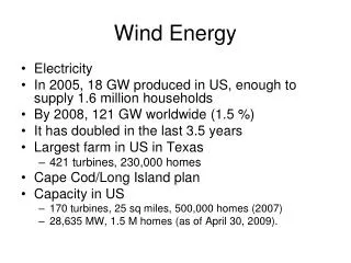
Introduction • Wind energy is a promising energy and becomes increasingly popular. • The cost of wind-generated electric power has dropped substantially. • By 2005, the worldwide capacity had been increased to 58,982 megawatts • World Wind Energy Association expects 120,000 MW to be installed globally by 2010.
Introduction Total installed wind power capacity (data fromWorld Wind Energy Association)
Introduction • Wind Energy Conversion System (WECS) • Stand alone • Electric Grid Connected WECS • Distributed/Dispersed Renewable Wind Energy • Located close to where the power is needed • Low reliability
Motivations • Energy crisis • Shortage of conventional fuel based energy • escalating prices • Environmental Issues • Greenhouse gas emission • Acid rain • Water pollution
Motivations • Large wind farm emerging (in the range of several megawatts) • Many new interface requirements regarding the full integration of large dispersed wind power into the power grid
Motivations • Challenges for the gird integration of the dispersed wind energy • Highly variable wind power injected into the grid • Increased penetration of wind energy • Electrically weak distribution networks - Radial structure - Large R/X ratio distribution line • Heavy reactive power burden brought by the induction generator
System Description L.L.1 L.L.2 T2 T3 N.L.L T1 Infinite Bus L.L.3 WECS I.M.
System Description-WECS Uncontrolled Rectifier PWM Inverter I.G. Lf To Grid Cf DC Link Interface Wind Turbine Cself
System Description-wind turbine • Wind turbine model based on the steady-state power characteristics of the turbine • S -- the area swept by the rotor blades (m^2) • v -- the wind velocity (m/s) • ρ--air density (kg/v^3)
System Description tip speed ratio λ is the quotient between the tangential speed of the rotor blade tips and the undisturbed wind velocity C1=0.5176, C2=116, C3=0.4, C4=5, C5=21 and C6=0.0068
System Description – Wind speed • The dynamic wind speed model consists of four basic components: • Mean wind speed-14 m/s • Wind speed ramp with a slope of ±5.6 • Wind gust • Ag: the amplitude of the gust • Tsg: the starting time of the gust • Teg: the end time of the gust • Dg = Teg - Tsg • Turbulence components: a random Gaussian series
System Description – Wind speed The eventual wind speed applied to the wind turbine is the summation of all four key components.
MPFC Scheme • Complementary PWM pulses to ensure dynamic topology change between switched capacitor and tuned arm power filter • Two IGBT solid state switches control the operation of the MPFC via a six-pulse diode bridge
Tri-loop Error Driven Controller Modulation Index Voltage Stabilization loop Current Harmonic Tracking Loop Current Dynamic Error Tracking loop
DVR Scheme If S1 is high and S2 is low, both the series and shunt capacitors are connected into the circuit, while the resistor and inductor will be fully shorted • A combination of series capacitor and shunt capacitor compensation • Flexible structure modulated by a Tri-loop Error Driven Controller If S1 is low and S2 is high, the series capacitor will be removed from the system, the resistor and inductor will be connected to the shunt capacitors as a tuned arm filter
HPFC Scheme • Use of a 6-pulse VSC based APF to have faster controllability and enhanced dynamic performance • Combination of tuned passive power filter and active power filter to reduce cost Coupling capacitor Coupling transformer PWM converter Passive Filter tuned near 3rd harmonic frequency DC Capacitor to provide the energizing voltage
Novel Decoupled Multi-loop Error Driven Controller • Using decoupled direct and quadrature (dq) voltage components • Using Phase Locked Loop (PLL) to get the synchronizing signal – the phase angle of the VSC output voltage • Using Proportional plus Integral (PI) controller to regulate any tracked errors • Using Pulse Width Modulation with variable modulation index
Novel Decoupled Multi-loop Error Driven Controller • Outer voltage regulator: tri-loop dynamic error driven controller • The voltage stabilization loop • The current dynamic error tracking loop • The dynamic power tracking loop • Inner voltage regulator: control the DC capacitor charging and discharging voltage to ensure a near constant DC capacitor voltage
Controller Tuning • Parametric optimization: guided Trial-and-error method based on successive digital simulations • Minimize the objective function-Jo • Find optimal kp, ki and individual loop weightings (γ) to yield a near minimum Jo under different set-selections of the controller parameters
Digital Simulation • Validation is done by using digital simulation under a sequence of excursions: • Load switching • At t = 0.2 second, the induction motor was removed from bus 5 for a duration of 0.1 seconds; • At t = 0.4 second, linear load was removed from bus 4 for a duration of 0.1 seconds; • At t = 0.5 second, the AC distribution system recovered to its initial state. • Wind gusting changes modeled by dynamic wind speed model
Digital Simulation • Digital Simulation Environment: MATLAB /Simulink/Sim-Power • Using the discrete simulation mode with a sample time of 0.1 milliseconds • The digital simulations were carried out without and with the novel FACTS-based devices located at Bus 5 for 0.8 seconds
The frequency variation at the WECS interface without and with MPFC
The frequency variation at the WECS interface without and with DVR
The frequency variation at the WECS interface without and with HPFC
Comparison of Voltage THD with Different Compensation Scheme
Comparison of Steady-state Bus Voltage with Different Compensation Scheme
Conclusions • Three FACTS-based schemes, namely the MPFC, the DVR, and the HPFC, have been proposed and validated for voltage stabilization, power factor correction and power quality improvement in the distribution network with dispersed wind energy integrated.
Recommendation • The MPFC is preferred for low to medium size wind energy integration schemes (from 600 to 5000 kW). • The DVR is good for the AC sub-transmission and distribution systems with large X/R ratio • The HPFC is suitable for the high wind-energy penetration level (100 MW or above).
Recommendation • The schemes validated in this research need to be fully tested in the distribution network with real dispersed wind energy systems. • This research can be extended to the grid integration of other dispersed renewable energy. • Other Artificial Intelligence based control strategies can be investigated in future work.
Conclusions • Developed a unified sample system model using the MATLAB/Simulink • Developed a simple dynamic wind speed model, which is suitable to simulate the stochastic and temporal wind variations in the MATLAB/Simulink • Validated the effectiveness of the proposed schemes by digital simulations • Determined the near optimum parameters of the proposed compensators with dynamic multi-loop error-driven controllers
Publications • [1] A. M. Sharaf and Weihua Wang, ‘A Low-cost Voltage Stabilization and Power Quality Enhancement Scheme for a Small Renewable Wind Energy Scheme’, 2006 IEEE International Symposium on Industrial Electronics, 2006, p.1949-53, Montreal, Canada • [2] A. M. Sharaf and Weihua Wang, ‘A Novel Voltage Stabilization Scheme for Standalone Wind Energy Using A Dynamic Sliding Mode Controller’, Proceeding- the 2nd International Green Energy Conference, 2006, Vol. 2, p.205-301, Oshawa, Canada • [3] A. M. Sharaf, Weihua Wang, and I. H. Altas, ‘Novel STATCOM Controller for Reactive Power Compensation in Distribution Networks with Dispersed Renewable Wind Energy’, 2007 Canadian Conference on Electrical and Computer Engineering, Vancouver, Canada, April, 2007 • [4] A. M. Sharaf, Weihua Wang, and I. H. Altas, ‘A Novel Modulated Power Filter Compensator for Renewable Dispersed Wind Energy Interface’, the International Conference on Clean Electrical Power, 2007, Capri, Italy, May, 2007 • [5] A. M. Sharaf, Weihua Wang, and I. H. Altas, ‘A Novel Modulated Power Filter Compensator for Distribution Networks with Distributed Wind Energy’ (Accepted by International Journal of Emerging Electric Power System)