Download
1 / 56
630 likes | 1.03k Views
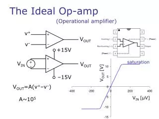
Analog Electronics Class 2: Ideal Op-Amp Analysis. Sep 9, 2011. Ideal Op-Amp. Voltage Controlled Voltage Source. Ideal Op-Amp Characteristics. Open Loop Voltage Gain (A vol ) is infinite Input offset Voltage is zero Input bias current is zero No power supply limits

E N D
Analog Electronics Class 2:Ideal Op-Amp Analysis Sep 9, 2011
Ideal Op-Amp Characteristics • Open Loop Voltage Gain (Avol) is infinite • Input offset Voltage is zero • Input bias current is zero • No power supply limits • Input impedance is infinite • Simple model is a voltage controlled voltage source with high gain.
Feedback Analogy Scotty Increase the output voltage! The input offset voltage is not zero! I’ll try caption, but I’m giving her all she’s got!
Simple Ideal Amp Analysis
Simple Analysis for Inverting Amp Vin across Rin • Iin flows through Rf • Vout is the voltage across Rf
Simple Analysis for Inverting Amp Find the same transfer function algebraically
Current Reference VR1 = VREF = 10V IGND≠0A IB=0A The voltage from noninverting input to the output is zero (i.e. no Vosi).
Probe Different Nodes You can probe any node. In this case I am probing V3. Voltage at meters is displayed. Vout = -4V
Circuits to Memorize
Common Amplifiers Buffer Vout = Vin
Superposition principle • Used for circuits with multiple input sources. • Analyze the output response for one source at a time. • Short unused voltage sources • Open unused current sources • Repeat the analysis for each source • Add all the response from each analysis to get the overall system respones
Superposition Example 2: Single Supply Amp (Noninverting)
Cf – Filter (High Gain) • At high frequency CF will short RF • High Freq Gain = 0/1k+1 = 1 • At low frequency CF acts like an open • DC Gain = (99k/1k)+1 = 100
Low Frequency Gain = 100 (40dB) High Frequency Gain = 1 (0dB) Zero at f= 16.08kHz 40dB / 20dB/dec = 2 decades. -45o / decade +45o / decade
Cf – Filter (Low Gain) • At high frequency CF will short RF • High Freq Gain = 0/1k+1 = 1 • At low frequency CF acts like an open • DC Gain = (2k/1k)+1 = 3
Low Frequency Gain = 3 (9.54dB) High Frequency Gain = 1 (0dB) Zero -45o / decade +45o / decade
The inverting amp with Cf • At high frequency CF will short RF • High Freq Gain =- 0/1k = 0 • At low frequency CF acts like an open • DC Gain = -(2k/1k) = -2
Comparing responses in Tina(Non-inverting vs. Inverting) • Use “control-C” to copy the graph. • Use the tabs (see bottom) to change plots. • Use “control-V” to past the response into a different plot
Nodal Analysis
Nodal Analysis • Sum of all currents at a node is zero • Assume all currents flow out of node • Assume node is the highest voltage potential • For Op-Amps • Ib = 0A • Vosi = 0V (voltage between op-amp inputs)
Mathcad: A New Tool
Mathcad • Does symbolic analyses of transfer functions • Substitute, Simplify, and Solve Equations • Numerical evaluation of complex expressions • Document your work • Mathcad is not a number crunching software package like Matlab or Mathematica
Select the expression and press control-C. Select the variable that you want to substitute. Use menu option: Symbolics\Variable\Substitute The expression with the substitution will appear below. This expression is simplified.
Select the variable that you want to simplify. Use menu option: Symbolics\Simplify Result of simplification
Evaluate an expression for specific values. Note the equal sign is different for evaluations then symbolic. “CTRL =“ Used for symbolic “:” used for numeric evaluation
Past function here. Past independent variable here. Adjust axis scale as needed.
Diodes and Transient Analysis
Select sine wave, amplitude, and period. Click on Vg1 to edit signal. Click on “…” button to edit signal.
Select transient analysis. Result window Adjust period to match signals period (5 x period in this example).
Add the diode into the circuit and run the same transient analysis.
Half wave rectifier. Note: the forward voltage is zero. The op-amp makes the diode ideal.