Download
1 / 23
230 likes | 305 Views
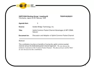
WP-CDMA Distinguishing Features. 1.Uplink Common Packet Channel (All Rates). Common Packet Channel will transport all data rates up to. and including 2.048 Mbps. Constant Power Level Preamble with 16 possible sequences. Closed Loop Power Control, Preamble Ramp-up mechanism.

E N D
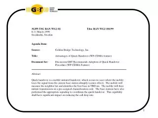
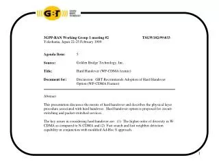
WP-CDMA Distinguishing Features 1.Uplink Common Packet Channel (All Rates) Common Packet Channel will transport all data rates up to and including 2.048 Mbps. Constant Power Level Preamble with 16 possible sequences • Closed Loop Power Control, Preamble Ramp-up mechanism • Fast L1 ACK mechanism (within 250 micro-seconds) • Collision Detection with Low Feedback Delay (2 ms) • Downlink Common Power Control Structure 2. Common Control Channel in the Down Link 3. Intra-frequency Hard Handover 4. Quick Handover 5. Structure of the WP-CDMA CCPCH (Common Control Physical Channel) • TM Common Pilot for coherent demodulation • Adjustable Power SCH1 And SCH2 for faster initial cell search 6. Multi-code Option for Higher Rates • The relationship between the VSF and number of multi-codes is the subject of • further study 7. Higher APC Rates 8. Removal of Link Maintenance Channel
What are the Information Transfer and Information Quality Attributes of These Services? Information Transfer Attribute Connection Mode Connectionless, Connection- oriented Traffic type attribute CBR, VBR, ABR, UBR Symmetry attribute Bi, Uni Information transfer rate 12 kbps, 2 Mbps Information Quality Attribute Maximum transfer delay 80 ms, 1 s, 30 s Delay variation –6 –9 Bit Error Rate 10 , 10 Error Characteristics Bursty, uniform
How can the Common Air Interface be Optimized for Packet Data Services? The CAI should be able to support high bit rates (up to 2 Mbps), · bursty, asymmetric, non-real time bearer capabilities The CAI should support the connectionless mode as well as the · connection-oriented modes The CAI should be able to support packet switching as well as · circuit switching transfer modes The QoS on demand and flexibility to provision various information · quality attributes per connection (implications on physical layer, the MAC and DLC) Minimize interworking functionality · Maintain the same QoS in the wireline and wireless systems · Minimize interference at the air interface · Minimize resource requirement at the base station · Optimize the IP protocol suite for the air interface · Implementation of optimum bandwidth allocation at the air interface ·
WP-CDMA Distinguishing Features Common Packet Channel (All Rates) • Common Packet Channel will transport all data rates up to and • including 2.0489 Mbps. • Constant Power Level Preamble with 16 possible sequences • Closed Loop Power Control, Preamble Ramp-up mechanism • Fast L1 ACK mechanism (within 250 micro-seconds) • Collision Detection with Low Feedback Delay (2 ms) • Downlink Common Control Channel Structure
F A B A B B F F B User i + 3 Packet 1 User i + 2 Packet 1 User i+3 Packet 1 E User i Packet User i+1 Packet WP-CDMA Common Packet Channel Uplink MOB ID MOB ID MOB ID A M CPCH UL User i+1 Packet User i Packet E M M E M F = Free A = ACK B = Busy Mob ID = Temp ID for Collision Detection E = End M = More
Short Term Circuit Assignment t Packet 1 Packet 2 Packet 3 i User i T inactivity Packet 1 Packet 2 t i+1 User i+1 t i T inactivity Packet 1 Packet 2 Packet 3 Packet 4 t i+2 t i+1 User i+2 M T inactivity Packet 1 Packet 2 Packet 3 User n t n
Closed Loop Power Control Courtesy of AT&T Labs
3.5 3.416 3 2.5 R i , 19 R i , 10 R i , 1 2 1.5 1.419 1 0 2 4 6 8 10 12 14 1.25 l 13.25 i 8 144 kbps Capacity Ratio Versus Packet Length in Kbyte PB=2% 100% Duty Cycle Channel inactivity = 50 ms Channel inactivity = 500 ms Channel inactivity = 1 s Capacity Ratio P-S/C-S Packet Length in Kbyte Advantages of Statistical Multiplexing
9 8.176 Capacity Ratio 8 P-S/C-S Channel inactivity time = 1 s Channel inactivity time = 500 ms 7 Channel inactivity time = 50 ms R 6 i , 19 R i , 10 R i , 1 5 4 3 2.85 2 0 5 10 15 20 25 30 2.5 l 27 i Packet Length in Kbyte 8 Advantages of Statistical Multiplexing 384 Kbps Capacity Ratio Versus Packet Length in Kbyte PB=2% 100% Duty Cycle
45 42.84 Capacity Ratio 40 Channel inactivity time = 1 s P-S/C-S Channel inactivity time = 500 ms 35 Channel inactivity time = 50 ms 30 R i , 19 R i , 10 25 R i , 1 20 15 10 7.427 5 5 10 15 20 25 30 35 40 45 5 l 42 i 8 Packet Length in Kbyte Advantages of Statistical Multiplexing 2048 Kbps Capacity Ratio Versus Packet Length in Kbyte PB=2% 100% Duty Cycle
UL-CPCH Burst Structure Data/Control Preamble ramp-up I Q N x TBD ms 1 ms .25 ms
UL-CPCH Slot Structure .625 ms, 10 x 2k bits (k=0,….6) Data I UL-CPCH N data bit 1 Slots 0 Pilot TPC CD bits RI Q UL-CPCH NTPC bits NRIbits N pilot bits NCD Data UL-CPCH I N data bit 1 Slots 1 Pilot RI TPC Q UL-CPCH NRI bits NTPC bits N pilot bits
UL-CPCH Frame Structure .625 ms, 10 x 2k bits (k=0,….6) Data UL-CPCH I N data bit 1 Pilot RI TPC Q UL-CPCH NRI bits NTPC bits N pilot bits Slot #1 Slot #2 Slot #i Slot #16 Tf = 10 ms
Power Control L1 ACK DL-CCCH Data UL-CPCH N x TBD ms 1 ms .25 ms TBD Procedure Based CCCH: Common Control Channel CPCH: Common Packet Channel Overall Protocol Operation
BS F 0 1 2 3 4 5 6 7 2.5 ms 8 mini-slots F BS DL-CCCH ACK CD TBD CD MS UL-CPCH Slot 0 625 s 1ms 250 s 1.875 ms Collision Feedback Delay Cycle
ARQ LI ACK PC CD CD ACK/NAK DL CCCH CD CD UL CPCH 1.25 ms Overall Protocol Operation
Throughput Performance of DSMA Impact of Low Collision Feedback Delay
Performance Advantages of Uplink Common Packet Channel (Summary-1) Proven improved throughput performance for short bursty traffic and high peak rate · • Sample pt: 384 kbps, L=4 Kbyte, Access overhead = 500 ms, P = 2% Throughput improvement Ratio = 5 B • UDD Services Improved delay performance of M/M/1 (packet switched) over · M/M/n (circuit switched) for longer packets Common Packet Channel approach requires an order of magnitude · less BS resources (modems) as compared to Short Term Circuit Assignment. • M/M/10 requires 10 times more modems in the BS as compared to M/M/1
Performance Advantages of CPCH-UL (Summary-2) • Statistical multiplexing advantages for bursty traffic • Less delay M/M/1 versus M/M/n • Resource minimization and less hardware complexity • Facilitation of higher peak rates • Queuing time & transmission time • Limitations of circuit switching trunking efficiency • Optimum prioritization scheme • Optimum bandwidth allocation in a mixed circuit-switched/packet switched • air interface operation in short time window (frame by frame basis)