Download
1 / 27
290 likes | 533 Views
Commissioning and performance of the ALICE TPC. Adam Matyja for the ALICE TPC co l laboration Subatech, Nantes & INP PAN Kraków. Outline Components of TPC Calibration Performance results Summary. The ALICE detector. *.

E N D
Commissioning and performance of the ALICE TPC Adam Matyja for the ALICE TPC collaboration Subatech, Nantes & INP PAN Kraków Outline • Components of TPC • Calibration • Performance results • Summary
The ALICE detector * * ALICE TPC Collaboration, J. Alme et al., "The ALICE TPC, a large 3-dimensional tracking device with fast readout for ultra-high multiplicity events.", Physics. Ins-Det/10011950 (2010)
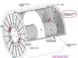
The principle of the Time Projection Chamber → Based on multi-wire proportional chamber • Charged particles ionize working gas atoms • Ionization electrons drift with the constant velocity (v) in the direction of readout chambers due to the electric field • Near the anode plane the strong electric field causes ionization avalanche • It induces the signal on the pad plane • It allows to obtain the information in two coordinates - (x,y) • The third coordinate is inferred from the measurement of the electrons drift time measurement (z=vt) • 3 coordinates give the space point on the track • Collected charge gives the information about the energy loss • Main tracking device • Allows to distinguish the charged particle species
ALICE Time Projection Chamber • General features: • Diameter Length: 5 m 5 m • Azimuth angle coverage: 2 • Pseudo-rapidity interval: ||<0.9 • Readout chambers: 72 • Drift field: 400 V/cm • Maximum drift time: 94 s • Central electrode HV: 100 kV • Gas: • Active volume: 90 m3 • Ne-CO2-N2: 85.7% - 9.5% - 4.8% • Cold gas - low diffusion • Non-saturated drift velocity temperature stability and homogeneity 0.1 K 5 m 2.5 m 2.5 m • Data readout: • Pads (3 types): 557 568 • Samples in time direction: 1000 • Data taking rate: • ~ 2.8 kHz for p-p • ~ 300 Hz for Pb-Pb
Components ReadOut Chambers • 2 sides with 18 sectors • Sector consists of: • Inner chamber (IROC) • Outer chamber (OROC) 72 readout chambers • Pad readout • 3 sizes • Stable operation
Components Drift voltage system Voltage dividers' network Provide constant electric field • Water cooled voltage dividers → remove dissipated power • Control of water conductivity • Radiation length X / X0of Field Cage • 1.367 % - inner FC • 0.607 % - gas • 2.153 % - outer FC Resistor rods • Very stable operation Few well understood trips (beam loss) • Tomography of FC in good agreement with MC
Components Recirculating gas system Precise control of gas mixture • O2 and H2O contamination removed by Cu catalyser • To minimize signal loss (e- attachment) • Contamination: ~ 1 ppm O2 (design < 5) • Humidity kept at fixed level → to avoid aging of components • In operation since 2006
FEC with its cooling envelope Components Cooling system Provide temperature stability • ~ 500 temperature sensors • Leakless underpressure system with ~ 60 adjustable cooling circuits • Thermal screening towards ITS and TRD • Copper shields of service support wheel • Cooling of ROC bodies • Water cooling of FEE in copper envelope (~27 kW) • Result: Temperature homogenity:T = 0.046 K Good agreement with design specifications
Components Detector Control System Ensure a safe and correct operation of TPC • Integrated into Experiment Control System • Hardware architecture • Supervisory layer: user interface (PC) + databases • Control layer: hub - collect & process information from supervisory and field layers • Field layer: electronics to control equipment (power supplies, FEE, …) • TPC is fully controlled by ALICE shifter
Calibration Noise measurements • Noise level improved during commissioning • Mean noise level: • 0.7 ADC count (700 e) • Designed - 1 ADC count (1000 e) • Data volume of empty event: • non-zero suppressed (ZS): ~ 700MB • ZS event: ~ 30kB • Typical size of the event with data: • 0.1 - 0.2 MB (p - p) • 360 kB TPC @ 7 TeV • ~ 30 MB (Pb - Pb, dN/dy = 2000) Current noise
Calibration Gain calibration using 83Kr • Resolution of main peak: • 4.0 % for IROCs • 4.3 % for OROCs OROC main peak (41.6 keV) Determine gain for each pad • Procedure: • Inject radioactive 83Kr • Characteristic decay spectrum • Dedicated clusterizer • Fit the main peak (41.6 keV) • Parabolic fit • Calibration constants • 3 different HV settings (gains) • High statistics: several 108 Kr events • Accuracy of peak position: << 1% (design: 1.5%) • Repeated after electronic maintenance or every year Gain variation Result: Relative gain variation C-side
Calibration Kr calibration - systematics Azimuth Radial OROC IROC long short mid Sector-by-sector Edge effect well visible → Parabolic fit applied to avoid it The shape reflects a mechanical deformation of the pad plane
Calibration Laser system The principle of laser system for the TPC • 336 laser beams • Used for: • E B effect • Drift velocity measurements • Alignment Laser features: • = 266 nm or E = h = 4.66 eV • Energy: 100 mJ/pulse • Duration of pulse: 5 ns The ionization in the gas volume along the laser path occurs via two photon absorption by organic impurities. Reconstructed laser tracks
Laser system Calibration E B effect Caused by: • Mechanical or electrical imperfections • Imperfect B field Correction map from laser tracks • Measure r • For each laser track • For several magnetic field settings • r 7 mm → for longest drift and nominal field • Corrected to ~ 0.3 mm • Detailed studies ongoing
Calibration Drift velocity measurements • d = d(E, B, (Tin, Patm), CCO2, CN2) • Crucial for track matching with other detectors • How to obtain drift velocity correction factor: • Matching laser tracks and mirror positions • Matching TPC and ITS tracks • Matching tracks from two halves of TPC • Drift velocity monitor • Required accuracy: 10-4 update every 1h • Photo electrons from central electrode monitor top-bottom arrival time offset caused by T and P gradients
Calibration Drift velocity measurements • d = d(E, B, (Tin, Patm), CCO2, CN2) • Crucial for track matching with other detectors • How to obtain drift velocity correction factor: • Matching laser tracks and mirror positions • Matching TPC and ITS tracks • Matching tracks from two halves of TPC • Drift velocity monitor • Required accuracy: 10-4 update every 1h Corrected spectrum • Photo electrons from central electrode monitor top-bottom arrival time offset caused by T and P gradients
Performance Space point resolution • Depends on: • Drift length • Inclination angle • Charge deposited on the anode wire • In r direction: Y = 300 - 800 m • for small inclination angles (high momentum tracks) • In drift direction: Z = 300 - 800 m • Good agreement with simulations
Performance Momentum resolution • High momentum tracks • Cosmic muon tracks treated independently in two halves of TPC • Comparison of pT at vertex gives resolution • Statistics: ~ 5 106 events • Low momentum tracks • Deduced from the width of K0S mass peak • Current status (w/o many corrections): (pT/pT)2 = (0.01)2 + (0.007pT)2 • Achieved: ~ 7 % @ 10 GeV/c ~ 1 % below 1 GeV/c • Place for improvement: ~ 4 % @ 10 GeV/c
Performance dE/dx resolution - cosmics TPC cosmic data d p Allows particle identification up to 50 GeV/c • Statistics: 8.3106 cosmic tracks in 2008 • Design goal: 5.5 % • Measured: < 5 % e 500 < p < 550 MeV e p
Performance dE/dx spectrum in data
Performance Material budget Radial distribution Vertices from conversion photons TPC begins here Agreement between MC and DATA: 5 ~ 15 %
Life of TPC • 2006 - first tests at the surface • No ZS • Only 2 sectors powered at a time • 2007 - first commissioning underground • C-side successfully operated • Online ZS • 2008 - commissioning with cosmics • Full TPC • Different run types implemented • Extensive calibration data taken _ • 06. 12. 2009 - first s = 900 GeV collisions _ • 30. 03. 2010 - first s = 7 TeV collisions
Summary • Physics results are well visible: • "Midrapidity antiproton-to-proton ratio in pp collisons at s = 0.9 and 7 TeV measured by the ALICE experiment." - Phys. Rev. Lett. 105.072002 (2010) • "Two-pion Bose-Einstein correlations in pp collisions at s = 900 GeV." - Phys. Rev. D 82, 052001 (2010) • "Transverse momentum spectra of charged particles in proton-proton collisions at s = 900 GeV with ALICE at the LHC." - submitted to PLB (arXiv:1007.0719) • Other papers to be submitted soon: • J/ production • Particle spectra • Strangeness • D(*)-mesons • ALICE TPC works stably during p-p data taking • Calibration done → working on improvements • Very good performance, close to specifications • We are waiting for Heavy Ions
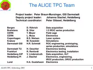
The ALICE TPC collaboration Harald Appelshaeuser6, Peter Braun-Munzinger7, Peter Christiansen9, Panagiota Foka7, Ulrich Frankenfeld7, Chilo Garabatos7, Peter Glassel8, Hans-Ake Gustafsson9, Haavard Helstrup1, Marian Ivanov7, Rudolf Janik2, Alexander Kalweit5, Ralf Keidel11, Marek Kowalski10, Dag Toppe Larsen1, Christian Lippmann3, Magnus Mager3, Adam Matyja10,12 , Luciano Musa3, Borge Svane Nielsen4, Helmut Oeschler5, Miro Pikna2, Attiq Ur Rehman3, Rainer Renfordt6, Stefan Rossegger3, Dieter Roehrich1, Hans-Rudolf Schmidt7, Martin Siska2, Brano Sitar2, Carsten Soegaard4, Johanna Stachel8, Peter Strmen2, Imrich Szarka2, Danilo Vranic7, Jens Wiechula8 • Department of Physics and Technology, University of Bergen, Bergen, Norway. • Faculty of Mathematics, Physics and Informatics, Comenius University, Bratislava, Slovakia. • European Organization for Nuclear Research (CERN), Geneva. • Niels Bohr Institute, University of Copenhagen, Copenhagen, Denmark. • Institut für Kernphysik, Technische Universität Darmstadt, Darmstadt, Germany. • Institut für Kernphysik, Johann-Wolfgang-Goethe Universität Frankfurt, Frankfurt, Germany. • Gesellschaft für Schwerionenforschung mbH (GSI), Darmstadt, Germany. • Physikalisches Institut, Ruprecht-Katls-Universität Heidelberg, Heidelberg, Germany. • Division of Experimental High Energy Physics, University of Lund, Lund, Sweden. • The Henryk Niewodniczański Institute of Nuclear Physics, Polish Academy of Sciences, Cracow, Poland. • Zentrum fur Technologietransfer und Telekommunikation (ZTT), Fachhochschule Worms, Worms, Germany. • Now at SUBATECH, Ecole des Mines de Nantes, Universite de Nantes, CNRS-IN2P3, Nantes, France.
Cluster finder Track Krypton Pad-row Pad-row Pad Pad Decay point Track Fired pad Fired pad Cluster Cluster