Download
1 / 4
40 likes | 99 Views
Learn about the effective length factor (K) and its importance in various frame conditions, including the differences between braced and unbraced frames. Explore alignment charts and calculations for columns in real-world engineering scenarios.

E N D
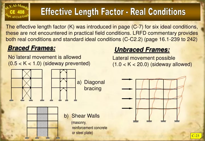
Effective Length Factor - Real Conditions The effective length factor (K) was introduced in page (C-7) for six ideal conditions, these are not encountered in practical field conditions. LRFD commentary provides both real conditions and standard ideal conditions (C-C2.2) (page 16.1-239 to 242) Braced Frames: Unbraced Frames: No lateral movement is allowed (0.5 < K < 1.0) (sideway prevented) Lateral movement possible (1.0 < K < 20.0) (sideway allowed) • Diagonal • bracing b) Shear Walls (masonry, reinforcement concrete or steel plate) C-23
Alignment Charts (LRFD P-16.1 - 241) where A is top of column where B is bottom of column * For fixed footing G = 1.0 * For pinned support G = 10.0 C-24
W12 x 96 12' W24 x 68 W24 x 55 A W12 x 120 12' W24 x 55 W24 x 68 B W12 x 120 15' C 18' 20' 20' Use of Alignment Charts Example C – 8 :- In the rigid frame shown below, Determine Kx for columns (AB) & (BC). Knowing that all columns webs are in the plane. Solution: Column (AB): Joint (A): C-25
For joint B,:- From the alignment chart for sideways uninhibited, with GA = 0.94 and GB = 0.95, Kx = 1.3 for column AB. Column (BC): For joint B, as before, G = 0.95 For joint C, at a pin connection the situation is analogous to that of a very stiff column attached to infinitely flexible girders – that is, girders of zero stiffness. The ratio of column stiffness to girder stiffness would therefore be infinite for a perfectly frictionless hinge. This end condition is only be approximated in practice, so the discussion accompanying the alignment chart recommends that G be taken as 10.0. From the alignment chart with GA = 0.95 and GB = 10.0, Kx = 1.85 for column BC. C-26