Download
1 / 75
750 likes | 776 Views
Future High Energy Particle Colliders in China. Introduction to CEPS-SppC Design Status. J. Gao IHEP, CAS, China ICHEP 2014, July 2-9, 2014, Valencia, Spain. Introduction CEPC SppC Concluding remarks. Contents. Lepton and Hadron Colliders’ History. CEPC+SppC

E N D
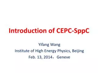
Future High Energy Particle Colliders in China Introduction to CEPS-SppC Design Status J. Gao IHEP, CAS, China ICHEP 2014, July 2-9, 2014, Valencia, Spain
Introduction • CEPC • SppC • Concluding remarks Contents
Lepton and Hadron Colliders’ History CEPC+SppC CEPC: Ecm=240GeV e+e- Circular Collider SppC: Ecm=50-100TeV pp Collider LC HIEPAF: High Intensity Electron Positron Accelerator Facility BEPC BEPCII History of BEPC 3 Old picture!
Strategy on High Energy Colliders in China • On “The 464th Fragrant Hill Meeting”, Chinese High Energy Physics Community arrived at the following consensus: 1) China supports ILC and will participate to ILC construction with in-kind contributions and requests R&D fund from government 2) After the discovery of Higgs, as next collider after BEPCII in China, a circular e+e- Higgs factory(CEPC)and a Super proton- proton Collier (SppC) afterwards in the same tunnel is an important option and historical opportunity. • On “The third China High Energy Physics based on Particle Accelerators”, Feb. 28, it was concluded that:“Circular e+e- Circular Higgs Factory(CEPC) +Super pp Collider (SppC) is the first choice for China’s future high energy physics accelerator.
CEPC-SppC Organization Steering Committee Y.F. Wang(IHEP) , Y.N. Gao (TU), J. Gao (IHEP),X.C. Lou (IHEP), Q. Qin (IHEP),H.J. Yang (SJTU),L. Han (USTC), S. Jin (IHEP), H.J. He (TU), S.H. Zhu (PKU), Y.J. Mao (PKU) Institutional Board Y.N. Gao (TU) J. Gao (IHEP) Project Directors X.C. Lou(IHEP) Q. Qin (IHEP) Theroy H.J. He (TU) S.H. Zhu (PKU) Accelerator Q. Qin (IHEP) J. Gao (IHEP) Detector S. Jin (IHEP) Y.N. Gao (TU)
Internationalization • This is a machine for the world and by the world: not a Chinese one • As a first step, “Center for Future High Energy Physics (CFHEP)”is established • Prof. Nima Arkani-Hamed is now the director • Many theorists(coordinated by Nima and Tao Han) and accelerator physicists(coordinated by Weiren Chou) from all the world have signed to work at CFHEP from weeks to months. • More are welcome need support from the related management • Current work: • Workshops, seminars, public lectures, working sessions, … • Pre-CDR • Future works (with the expansion of CFHEP) • CDR & TDR • Engineer design and construction • A seed for an international lab Organized and managed by the community • We established closely collaborate with FCC@CERN
A Good Start Many workshops, seminars in China and in the world • Sep. 2013, Dec. 2013, March. 2014, Oct. 2014… CEPC+SppC Kick off Meeting (Sept. 13-14,2013, Beijing)
CEPC-SppC and FCC • CERN started the Future Circular Collider effort since last year • FCC kick-off meting in Feb., 2014 • ICFA statement On Feb. 21, 2014 at DESY: ICFA supports studies of energy frontier circular colliders and encourages global coordination ICFA: international committee for Future accelerators http://www.fnal.gov/directorate/icfa/
Writing assigned for Pre-CDR(for example) • Visitors from other labs in the world participate the Pre-CDR joint works
Indico for CEPC AP meeting http://indico.ihep.ac.cn/categoryDisplay.py?categId=237
DocDB system for documents management • DocDB will be used for documents management • Server has been ordered
Introduction CEPC SppC Concluding remarks Contents
Sketch of CEPC In current design: • Circumference: 51.6 km • 16*arcs: 48.4km • 14*short straight: 14*144m=2.0km • 2*IPs:2*576m=1.2km • 8 RF cavities are uniformly distributed in every other straights. • The other 6 straights can be used for injection and dump.
Lattice of arc sections • Dispersion suppressor on each side of every arc • Length: 96m • Length of FODO cell: 48m • Phase advance of FODO cells: 60/60 degrees
Lattice of straight sections • FFS is temporarily replaced by FODO cells • Length of each IP section: 576m • Used for workpoint adjustment • Length straight: 144m • Phase advance of FODO cells: 60/60 degrees
Dynamic aperture of the MR • 2 families of sextupoles are used for chromaticity correction • Working point of the ring (.08,.22) • Achieved dynamic aperture: ~100sx/1500sy
Pretzelscheme • Use 2 pairs of electrostatic separators • Beam separated at horizontal plane with orbit offset of 5sx • Maximum bunch number: 96
Original FFS design by Dou WANG betaX*=0.8m betaY*=0.0012m L*=2.5m IP Total length: 670 m
Newest FFS design based on Yunhai’s idea IP betaX*=0.8m betaY*=0.0012m L*=2.5m Half Quad of dispersion suppressor FFS entrance condition: DX=DPX=0 x=y=0 betax=84m betaY=28m Total length: 170 m • We use the same method as Yunhai’s example to make a new design of CEPC FFS.
Dynamic Aperture-FFS 170m(Zero sextupole length) On momentum Off momentum: 2%, 1%
Dynamic Aperture-FFS 170m(finite sextupole length) On momentum Off momentum: 2%, 1%
Dynamic Aperture-FFS 170m FFS:170m 六级铁长度L=0.3m εx =7.67nm εy =εx/330=0.0232nm βx=0.8m βy=0.0012m σx=78 μm σy = 0.167 μm 10.8σy 2%,-2%的孔径是0 On momentum 0.64σx 1%,-1%
CEPC Beam-beam simulation (Ohmi’s) The current main parameters has been checked with beam-beam simulation, proved the reasonability. It seems bety~2mm better than 1.2mm from luminosity and transverse distribution
Tune diagram of CEPC lattice According to Ohmi’s simulation results, we choose the Work point: (179.08, 179.22) IHEP, Beijing, China
Primary calculations for Synchrotron Radiation Parameters at CEPC ring • The radiated critical photon energy • The flux density at the forward (direction(photons/s/mr2/0.1%bandwidth) • The total emitted power in each bending magnet
Synchrotron Radiation at CEPC • Synchrotron Radiation Parameters calculated • realizable shielding structure design for the beam pipe can be critical • LEP vacuum chamber structure was adopted preliminary • Shielding model and method were important • Simulation programs: FLUKA & MCNP • Model building and simulation were independently for verification • Primary shielding simulating results focus on • The correct method/model for shielding simulation • Gamma flux/spectrum/attenuation VS different Pb thickness
CEPC bending magnet synchrotron radiation brightness
CEPC undulator and wiggler synchrotron radiation brightness
RF System Distribution • Total number of module: 109 • 4 cavities/module, 7m/module • Total length: 7m*109=763m • 8 RF districts • 14module/district*5+13module/district*3 • Length of district: 98m&91m • Klystron number:109 • 1klystron/module
CEPC RF System Cryogenic Loss CEPC four 5-cell 700 MHz cavity string (moderate technical challenge): • HOM coupler (modes below cut-off frequency < ~ kW; or larger beam pipe, no cut-off); extra cryogenic load to be calculated. • HOM damper at room temperature (4.9 kW each damper); HOM damper at 80-100 K (forbidden by cryogenics load: 80 K cryo efficiency 16 W/W)
CEPC Multi Bunch Effects No instability issues. There is no heavy instabilities if Qe<104.Need both cold HOMcouplers and warm HOM absorbers for the 5-cell cavity. Detailed HOM damping design later.
Impedance budget • Resistive wall impedance is calculated with analytical formulas • Impedance of the RF cavities is calculated with ABCI
Longitudinal microwave instability • Keil-Schnell criterion: • The threshold of the longitudinal impedance is |Z///n| < 0.026 . Steady-state bunch shape Pseudo-Green function wake (z=0.5mm)
Coherent synchrotron radiation • z1/2/h3/2=35.2 (=> CSR shielded) • The threshold of bunch population for CSR is given by • The CSR threshold in BAPS is Nb,Th = 1.51013 >> Nb = 3.71011. • CSR is not supposed to be a problem in BAPS. (K. Bane, Y. Cai, G. Stupakov, PRST-AB, 2010) • Space charge tune shift y = 1.8e4, x = 5.2e6
Transverse mode coupling instability (TMCI) • The threshold of transverse impedance is |Z| < 11.7 M/m. • The equivalent longitudinal impedance is 0.18 , which is much larger than that of the longitudinal instability. • Eigen mode analysis • Considering only resistive wall impedance • Beam current threshold: Ibth=0.76mA (I0th=38mA)
Multi-bunch effects • Transverse resistive wall instability with wpn = 2pfrev (pnb + n + nx,y) • The growth rate for the most dangerous instability mode is 36 Hz (=28 ms)in the vertical plane with mode number of = 21. • The growth time is higher than the transverse radiation damping time. • The resistive wall instability is not supposed to happen in the main ring! Growth rate vs. mode number in the vertical plane
Electron cloud instability • Threshold density for the single bunch effect is considerable high. • The phase angle for the multi-bunch effect is about two orders higher, so the electrons are not supposed to accumulate and the multipacting effects is low.
Beam ion instability • Ion trapping • With uniform filling pattern, the ions with a relative molecular mass larger than Ax,y will be trapped. • Fast beam ion instability • With uniform filling, the growth time considering ion oscillation frequency spread is 11ms, which is lower than the damping time. • Fast beam ion instability could occur with uniform filling. • The ions will not be trapped by the beam.
Beam lifetimes caused by different sources in CEPC • Quantum lifetime • Radiation Bhabha lifetime • Simulated by BBBREM