Download
1 / 50
500 likes | 723 Views
IM. Reg. DM. Reg. IM. Reg. DM. Reg. IM. Reg. DM. Reg. Forwarding. The actual result $1 - $3 is computed in clock cycle 3, before it’s needed in cycles 4 and 5 We forward that value to later instructions, to prevent data hazards:

E N D
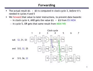
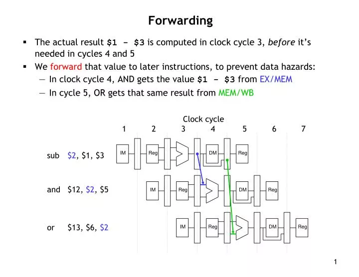
IM Reg DM Reg IM Reg DM Reg IM Reg DM Reg Forwarding • The actual result $1 - $3 is computed in clock cycle 3, before it’s needed in cycles 4 and 5 • We forward that value to later instructions, to prevent data hazards: • In clock cycle 4, AND gets the value $1 - $3 from EX/MEM • In cycle 5, OR gets that same result from MEM/WB Clock cycle 1 2 3 4 5 6 7 sub $2, $1, $3 and $12, $2, $5 or $13, $6, $2
IM Reg DM Reg IM Reg DM Reg IM Reg DM Reg Outline of forwarding hardware • A forwarding unit selects the correct ALU inputs for the EX stage: • No hazard: ALU’s operands come from the register file, like normal • Data hazard: operands come from either the EX/MEM or MEM/WB pipeline registers instead • The ALU sources will be selected by two new multiplexers, with control signals named ForwardA and ForwardB sub $2, $1, $3 and $12, $2, $5 or $13, $6, $2
0 1 IF/ID ID/EX EX/MEM MEM/WB PC 0 1 2 Registers ForwardA Instruction memory ALU 0 1 2 Data memory 1 0 ForwardB Rt Rd Simplified datapath with forwarding muxes
sub $2, $1, $3 or $12, $2, $5 IM IM Reg Reg DM DM Reg Reg Detecting EX/MEM Hazards • How to detect an impending hazard? • In the above case, it occurs in cycle 3, when sub is in EX, or is in ID • Hazard because: ID/EX.rd == IF/ID.rs • An EX/MEM hazard occurs between the instruction currently in its EX stage and the previous instruction if: • The previous instruction will write to the register file, and • The destination is one of the ALU source registers in the EX stage
IM IM Reg Reg DM DM Reg Reg sub $2, $1, $3 and $12, $2, $5 EX/MEM data hazard equations • The first ALU source comes from the pipeline register when necessary: if (EX/MEM.RegWrite and EX/MEM.rd == ID/EX.rs) ForwardA = 2 • The second ALU source is similar: if (EX/MEM.RegWrite and EX/MEM.rd == ID/EX.rt) ForwardB = 2
IM IM IM Reg Reg Reg DM DM DM Reg Reg Reg add $1, $2, $3 add $1, $1, $4 sub $5, $5, $1 MEM/WB data hazards • A MEM/WB hazard may occur between an instruction in the EX stage and the instruction from two cycles ago • One new problem is if a register is updated twice in a row: add $1, $2, $3 add $1, $1, $4 sub $5, $5, $1 • Register $1 is written by both of the previous instructions, but only the most recent result (from the second ADD) should be forwarded
MEM/WB hazard equations • Here is an equation for detecting and handling MEM/WB hazards for the first ALU source: if (MEM/WB.RegWrite and MEM/WB.rd == ID/EX.rs and (EX/MEM.rd ≠ID/EX.rs or not(EX/MEM.RegWrite)) ForwardA = 1 • The second ALU operand is handled similarly: if (MEM/WB.RegWrite and MEM/WB.rd == ID/EX.rt and (EX/MEM.rd ≠ID/EX.rt or not(EX/MEM.RegWrite)) ForwardB = 1 • Handled by a forwarding unit which uses the control signals stored in pipeline registers to set the values of ForwardA and ForwardB
0 1 IF/ID ID/EX EX/MEM MEM/WB 0 1 2 PC ForwardA Registers Instruction memory ALU 0 1 2 Data memory 1 0 ForwardB Rt Rd EX/MEM.RegisterRd Rs ID/EX. RegisterRt Forwarding Unit MEM/WB.RegisterRd ID/EX. RegisterRs Simplified datapath with forwarding
Example sub $2, $1, $3 and $12, $2, $5 or $13, $6, $2 add $14, $2, $2 sw $15, 100($2) • Assume again each register initially contains its number plus 100 • After the first instruction, $2 should contain -2 (= 101 - 103) • The other instructions should all use -2 as one of their operands • We’ll try to keep the example short: • Assume no forwarding is needed except for register $2 • We’ll skip the first two cycles, since they’re the same as before
0 1 PC Clock cycle 3 IF: or $13, $6, $2 ID: and $12, $2, $5 EX: sub $2, $1, $3 IF/ID ID/EX EX/MEM MEM/WB 101 2 0 1 2 102 101 5 0 Registers Instruction memory ALU 103 X 0 1 2 105 103 -2 Data memory X 1 0 0 5 (Rt) 2 12 (Rd) 2 EX/MEM.RegisterRd 2 (Rs) ID/EX. RegisterRt Forwarding Unit 3 ID/EX. RegisterRs 1 MEM/WB.RegisterRd
0 1 PC Clock cycle 4: forwarding $2 from EX/MEM IF: add $14, $2, $2 ID: or $13, $6, $2 EX: and $12, $2, $5 MEM: sub $2, $1, $3 IF/ID ID/EX EX/MEM MEM/WB 102 6 0 1 2 106 -2 2 2 Registers Instruction memory ALU -2 105 X 0 1 2 102 105 104 Data memory X 1 0 0 2 (Rt) 12 13 (Rd) 12 EX/MEM.RegisterRd 6 (Rs) ID/EX. RegisterRt 2 Forwarding Unit 5 2 MEM/WB.RegisterRd ID/EX. RegisterRs -2
0 1 PC Clock cycle 5: forwarding $2 from MEM/WB MEM: and $12, $2, $5 IF: sw $15, 100($2) ID: add $14, $2, $2 EX: or $13, $6, $2 WB: sub $2, $1, $3 IF/ID ID/EX EX/MEM MEM/WB 106 2 0 1 2 -2 106 2 0 Registers Instruction memory ALU 104 102 2 0 1 2 -2 -2 -2 Data memory -2 -2 X 1 0 -2 1 2 (Rt) 13 14 (Rd) 13 EX/MEM.RegisterRd 2 2 (Rs) ID/EX. RegisterRt 12 Forwarding Unit 2 ID/EX. RegisterRs 6 MEM/WB.RegisterRd 2 104 -2
Forwarding resolved two data hazards • The data hazard during cycle 4: • The forwarding unit notices that the ALU’s first source register for the AND is also the destination of the SUB instruction • The correct value is forwarded from the EX/MEM register, overriding the incorrect old value still in the register file • The data hazard during cycle 5: • The ALU’s second source (for OR) is the SUB destination again • This time, the value has to be forwarded from the MEM/WB pipeline register instead • There are no other hazards involving the SUB instruction • During cycle 5, SUB writes its result back into register $2 • The ADD instruction can read this new value from the register file in the same cycle
0 1 PC 0 1 2 0 1 2 0 1 Forwarding Unit Complete pipelined datapath...so far ID/EX EX/MEM WB Control MEM/WB M WB IF/ID EX M WB Read register 1 Read data 1 Addr Instr Read register 2 ALU Zero ALUSrc Write register Read data 2 Result Address Instruction memory Data memory Write data Registers Write data Read data Instr [15 - 0] 1 0 RegDst Extend Rt Rd EX/MEM.RegisterRd Rs MEM/WB.RegisterRd
IM IM Reg Reg DM DM Reg Reg What about stores? • Two “easy” cases: 1 2 3 4 5 6 add $1, $2, $3 sw $4, 0($1) IM Reg DM Reg 1 2 3 4 5 6 add $1, $2, $3 sw $1, 0($4) IM Reg DM Reg
PC Store Bypassing: Version 1 MEM: add $1, $2, $3 EX: sw $4, 0($1) IF/ID ID/EX EX/MEM MEM/WB Read register 1 Read data 1 0 1 2 Addr Instr Read register 2 ALU Zero ALUSrc Write register Read data 2 Result Address 0 1 2 Instruction memory 0 1 Data memory Write data Registers Write data Read data Instr [15 - 0] 1 0 RegDst Extend Rt 0 1 Rd EX/MEM.RegisterRd Rs Forwarding Unit MEM/WB.RegisterRd
PC Store Bypassing: Version 2 MEM: add $1, $2, $3 EX: sw $1, 0($4) IF/ID ID/EX EX/MEM MEM/WB Read register 1 Read data 1 0 1 2 Addr Instr Read register 2 ALU Zero ALUSrc Write register Read data 2 Result Address 0 1 2 Instruction memory 0 1 Data memory Write data Registers Write data Read data Instr [15 - 0] 1 0 RegDst Extend Rt 0 1 Rd EX/MEM.RegisterRd Rs Forwarding Unit MEM/WB.RegisterRd
IM Reg DM Reg What about stores? • A harder case: • In what cycle is the load value available? • End of cycle 4 • In what cycle is the store value needed? • Start of cycle 5 • What do we have to add to the datapath? 1 2 3 4 5 6 lw $1, 0($2) sw $1, 0($4) IM Reg DM Reg
PC Load/Store Bypassing: Extend the Datapath ForwardC 0 1 IF/ID ID/EX EX/MEM MEM/WB Read register 1 Read data 1 0 1 2 Addr Instr Read register 2 ALU Zero ALUSrc Address Write register Read data 2 Result 0 1 2 Instruction memory 0 1 Data memory Write data Registers Write data Read data Instr [15 - 0] 1 0 RegDst Extend Rt 0 1 Rd EX/MEM.RegisterRd Rs Forwarding Unit Sequence : lw $1, 0($2) sw $1, 0($4) MEM/WB.RegisterRd
Miscellaneous comments • Each MIPS instruction writes to at most one register • This makes the forwarding hardware easier to design, since there is only one destination register that ever needs to be forwarded • Forwarding is especially important with deep pipelines like the ones in all current PC processors • The textbook has some additional material not shown here: • Their hazard detection equations also ensure that the source register is not $0, which can never be modified
Load-Use Data Hazard Need to stall for one cycle
What about loads? Consider the instruction sequence shown below: The load data doesn’t come from memory until the end of cycle 4 But the AND needs that value at the beginning of the same cycle! This is a “true” data hazard—the data is not available when we need it We call this a load-use hazard IM Reg DM Reg IM Reg DM Reg Clock cycle 1 2 3 4 5 6 lw $2, 20($3) and $12, $2, $5 22
Stalling The easiest solution is to stall the pipeline We could delay the AND instruction by introducing a one-cycle delay into the pipeline, sometimes called a bubble Notice that we’re still using forwarding in cycle 5, to get data from the MEM/WB pipeline register to the ALU IM Reg DM Reg Clock cycle 1 2 3 4 5 6 7 lw $2, 20($3) and $12, $2, $5 IM Reg DM Reg 23
Stalling and forwarding Without forwarding, we’d have to stall for two cycles to wait for the LW instruction’s writeback stage In general, you can always stall to avoid hazards—but dependencies are very common in real code, and stalling often can reduce performance by a significant amount IM Reg DM Reg Clock cycle 1 2 3 4 5 6 7 8 lw $2, 20($3) and $12, $2, $5 IM Reg DM Reg 24
Load-Use Hazard Detection • Check when using instruction is decoded in ID stage • ALU operand register numbers in ID stage are given by • IF/ID.RegisterRs, IF/ID.RegisterRt • Load-use hazard when • ID/EX.MemRead and ((ID/EX.RegisterRt = IF/ID.RegisterRs) or (ID/EX.RegisterRt = IF/ID.RegisterRt)) • If detected, stall and insert bubble
How to Stall the Pipeline • Force control values in ID/EX registerto 0 • EX, MEM and WB do nop (no-operation) • Prevent update of PC and IF/ID register • Using instruction is decoded again • Following instruction is fetched again • 1-cycle stall allows MEM to read data for lw • Can subsequently forward to EX stage
Stalling delays the entire pipeline If we delay the second instruction, we’ll have to delay the third one too This is necessary to make forwarding work between AND and OR It also prevents problems such as two instructions trying to write to the same register in the same cycle IM Reg DM Reg Clock cycle 1 2 3 4 5 6 7 8 lw $2, 20($3) and $12, $2, $5 or $13, $12, $2 IM Reg DM Reg IM Reg DM Reg 27
But what about the ALU during cycle 4, the data memory in cycle 5, and the register file write in cycle 6? Those units aren’t used in those cycles because of the stall, so we can set the EX, MEM and WB control signals to all 0s. What about EX, MEM, WB IM Reg DM Reg Clock cycle 1 2 3 4 5 6 7 8 lw $2, 20($3) and $12, $2, $5 or $13, $12, $2 IM Reg Reg DM Reg IM IM Reg DM Reg 28
Detecting Stalls, cont. When should stalls be detected? EX stage (of the instruction causing the stall) IM Reg DM Reg lw $2, 20($3) and $12, $2, $5 mem\wb ex/mem id/ex if/id mem\wb IM Reg Reg DM Reg id/ex ex/mem if/id if/id • What is the stall condition? if (ID/EX.MemRead = 1 and (ID/EX.rt = IF/ID.rs or ID/EX.rt = IF/ID.rt)) then stall 29
Adding hazard detection to the CPU 0 1 ID/EX.MemRead Hazard Unit ID/EX.RegisterRt ID/EX 0 IF/ID Write Rs Rt 0 1 EX/MEM WB PC Write MEM/WB M WB PC Control EX M WB IF/ID Read register 1 Read data 1 0 1 2 Addr Instr Read register 2 ALU Zero ALUSrc Write register Read data 2 Result Address 0 1 2 Instruction memory 0 1 Data memory Write data Registers Write data Read data Instr [15 - 0] 1 0 RegDst Extend Rt Rd EX/MEM.RegisterRd Rs Forwarding Unit MEM/WB.RegisterRd 30
Stalls and Performance • Stalls reduce performance • But are required to get correct results • Compiler can arrange code to avoid hazards and stalls • Requires knowledge of the pipeline structure
Code Scheduling to Avoid Stalls Reorder code to avoid use of load result in the next instruction Ex: c code for A = B + E; C = B + F; lw $t1, 0($t0) lw $t2, 4($t0) add $t3, $t1, $t2 sw $t3, 12($t0) lw $t4, 8($t0) add $t5, $t1, $t4 sw $t5, 16($t0) lw $t1, 0($t0) lw $t2, 4($t0) lw $t4, 8($t0) add $t3, $t1, $t2 sw $t3, 12($t0) add $t5, $t1, $t4 sw $t5, 16($t0) stall stall 13 cycles 11 cycles
Branches in the original pipelined datapath 1 0 0 1 Add Add When are they resolved? ID/EX EX/MEM WB PCSrc Control MEM/WB M WB IF/ID EX M WB 4 P C Shift left 2 RegWrite Read register 1 Read data 1 MemWrite ALU Read address Instruction [31-0] Zero Read register 2 Read data 2 0 1 Result Address Write register Data memory Instruction memory MemToReg Registers ALUOp Write data ALUSrc Write data Read data 1 0 Instr [15 - 0] Sign extend RegDst MemRead Instr [20 - 16] Instr [15 - 11] 33
Branch Hazards If branch outcome determined in MEM: Flush theseinstructions (Set controlvalues to 0) PC
Reducing Branch Delay Move hardware to determine outcome to ID stage • Target address adder • Register comparator Example: branch taken 36: sub $10, $4, $840: beq $1, $3, 744: and $12, $2, $548: or $13, $2, $652: add $14, $4, $256: slt $15, $6, $7 ...72: lw $4, 50($7)
IF IF IF IF ID ID ID ID EX EX EX EX MEM MEM MEM MEM WB WB WB WB Data Hazards for Branches If a comparison register is a destination of 2nd or 3rd preceding ALU instruction add $1, $2, $3 add $4, $5, $6 … beq $1, $4, target Can resolve using forwarding
IF IF ID ID EX EX MEM MEM WB WB Data Hazards for Branches If a comparison register is a destination of preceding ALU instruction or 2nd preceding load instruction Need 1 stall cycle lw $1, addr add $4, $5, $6 IF ID beq stalled ID EX MEM WB beq $1, $4, target
IF ID EX MEM WB Data Hazards for Branches If a comparison register is a destination of immediately preceding load instruction • Need 2 stall cycles lw $1, addr IF ID beq stalled ID beq stalled ID EX MEM WB beq $1, $0, target
Branch Prediction • Longer pipelines can’t readily determine branch outcome early • Stall penalty becomes unacceptable • Predict (i.e., guess) outcome of branch • Only stall if prediction is wrong • Simplest prediction strategy • predict branches not taken • Works well for loops if the loop tests are done at the start. • Fetch instruction after branch, with no delay
MIPS with Predict Not Taken Prediction correct Prediction incorrect
Dynamic Branch Prediction • In deeper and superscalar pipelines, branch penalty is more significant • Use dynamic prediction • Branch prediction buffer (aka branch history table) • Indexed by recent branch instruction addresses • Stores outcome (taken/not taken) • To execute a branch • Check table, expect the same outcome • Start fetching from fall-through or target • If wrong, flush pipeline and flip prediction
1-Bit Predictor: Shortcoming Inner loop branches mispredicted twice! outer: … …inner: … … beq …, …, inner … beq …, …, outer • Mispredict as taken on last iteration of inner loop • Then mispredict as not taken on first iteration of inner loop next time around
2-Bit Predictor Only change prediction on two successive mispredictions
Calculating the Branch Target • Even with predictor, still need to calculate the target address • 1-cycle penalty for a taken branch • Branch target buffer • Cache of target addresses • Indexed by PC when instruction fetched • If hit and instruction is branch predicted taken, can fetch target immediately
Concluding Remarks • ISA influences design of datapath and control • Datapath and control influence design of ISA • Pipelining improves instruction throughputusing parallelism • More instructions completed per second • Latency for each instruction not reduced • Hazards: structural, data, control • Main additions in hardware: • forwarding unit • hazard detection and stalling • branch predictor • branch target table
IM Reg DM Reg IM Reg DM Reg What about loads? • Consider the instruction sequence shown below: • The load data doesn’t come from memory until the end of cycle 4 • But the AND needs that value at the beginning of the same cycle! • This is a “true” data hazard—the data is not available when we need it • We call this a load-use hazard Clock cycle 1 2 3 4 5 6 lw $2, 20($3) and $12, $2, $5
IM Reg DM Reg Stalling • The easiest solution is to stall the pipeline • We could delay the AND instruction by introducing a one-cycle delay into the pipeline, sometimes called a bubble • Notice that we’re still using forwarding in cycle 5, to get data from the MEM/WB pipeline register to the ALU Clock cycle 1 2 3 4 5 6 7 lw $2, 20($3) and $12, $2, $5 IM Reg DM Reg
IM Reg DM Reg Stalling and forwarding • Without forwarding, we’d have to stall for two cycles to wait for the LW instruction’s writeback stage • In general, you can always stall to avoid hazards—but dependencies are very common in real code, and stalling often can reduce performance by a significant amount Clock cycle 1 2 3 4 5 6 7 8 lw $2, 20($3) and $12, $2, $5 IM Reg DM Reg