Download
1 / 14
140 likes | 265 Views
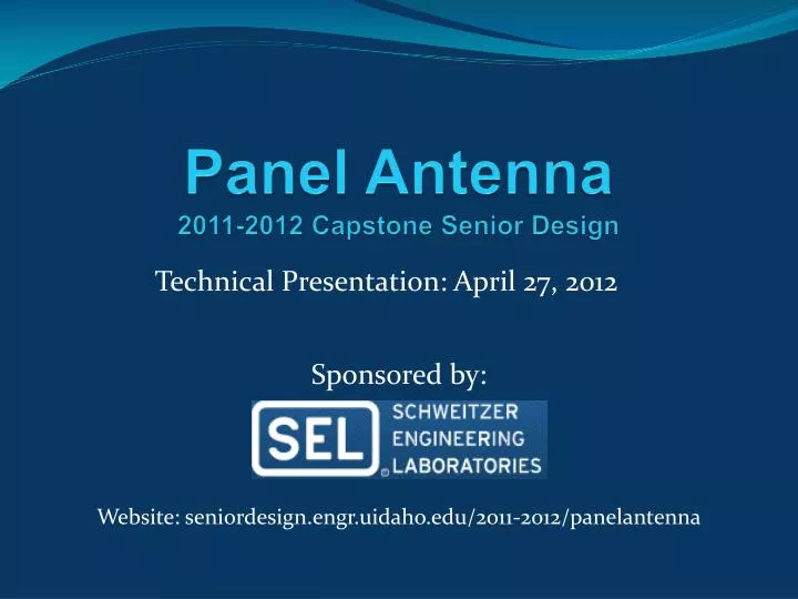
Panel Antenna 2011-2012 Capstone Senior Design. Technical Presentation: April 27, 2012. Sponsored by:. Website: seniordesign.engr.uidaho.edu/2011-2012/ panelantenna. The Team. Allan Davis: Project Lead Carlos Gonzalez: Budget/Resource Manager Cooper McBride: Website Developer. Objective.

E N D
Panel Antenna2011-2012 Capstone Senior Design Technical Presentation: April 27, 2012 Sponsored by: Website: seniordesign.engr.uidaho.edu/2011-2012/panelantenna
The Team • Allan Davis: Project Lead • Carlos Gonzalez: Budget/Resource Manager • Cooper McBride: Website Developer
Objective • Design, fabricate and test a 900-Mhz directional panel antenna for Schweitzer Engineering Laboratories
Applications • Radios provide comm channels for electric utility protection, monitoring, and control • Economical alternative to fiber-optic cable • Backup primary protection channels • Many more possible applications of wireless communications for critical infrastructure
What SEL Needs • An antenna that will have performance similar to antennas that are currently supplied by outside sources • The antenna will be used with the SEL-3031 Serial Radio Transceiver
Yagi Antenna • SEL is currently selling directional Yagi antennas with the SEL-3031 • An example of a 5-element Yagi is shown here
Design Process • Research of existing antenna designs • Computer simulations using Agilent EMPro software • Finite-difference time-domain (FDTD) • Finite element method (FEM) • We fabricated several design variations based on our simulation results • We tested the designs with different backplate spacings using SELs RFI chamber
Final Design • Directional Bowtie Antenna
Far-Field Radiation Patterns Simulated Tested Horizontal Plane Back Lobe Main Lobe Side Lobes Main Lobe
Specifications • Operating frequency range: 900-930 MHz • Directional • Used for either vertical or horizontal polarization • Gain ≈ 6 dBi • 3-dB Beamwidth ≈ 65° • Designed using printed circuit board technology • FR-4 substrate • Backplate spacing: 83 mm (λ/4)
Challenges during the project • Software • PC compatibility issues • Convergence issues • Simulation times ranged from ½ hour to 7 hours • Correctly interpreting simulation results • Extensive trial and error to get useable data • Limited availability of RFI chamber
Recommendations for future work • Investigate using an array of 2-4 bowtie elements for improved directionality • Match the input impedance to 50 Ω using a microstrip matching network (quarter-wave impedance transformer, etc.) • The antenna should be characterized by a professional antenna laboratory before production
Special Thanks • Advisors: • Dr. Greg Donohoe • Dr. TourajAssefi • Sponsors: • Eric Sagen • Henry Loehner • Dr. Jeff Young • Dr. Chris Wagner