Download
1 / 45
460 likes | 477 Views
This chapter discusses the LC-3 Instruction Set Architecture (ISA) which includes memory organization, register set, instruction set, addressing modes, data types, and more.

E N D
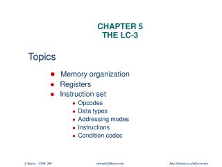
Instruction Set Architecture • ISA = All of the programmer-visible components and operations of the computer • memory organization • address space -- how may locations can be addressed? • addressibility -- how many bits per location? • register set • how many? what size? how are they used? • instruction set • opcodes • data types • addressing modes • ISA provides all information needed for someone that wants towrite a program in machine language(or translate from a high-level language to machine language).
LC-3 Overview: Memory and Registers • Memory • address space: 216 locations (16-bit addresses) • addressability: 16 bits • Registers • temporary storage, accessed in a single machine cycle • accessing memory generally takes longer than a single cycle • eight general-purpose registers: R0 - R7 • each 16 bits wide • how many bits to uniquely identify a register? • other registers • not directly addressable, but used by (and affected by) instructions • PC (program counter), condition codes
Instruction Processing: FETCH • Load next instruction (at address stored in PC) from memoryinto Instruction Register (IR). • Copy contents of PC into MAR. • Send “read” signal to memory. • Copy contents of MDR into IR. • Then increment PC, so that it points to the next instruction in sequence. • PC becomes PC+1. F D EA OP EX S
LC-3 Overview: Instruction Set • Opcodes • 15 opcodes • Operate instructions: ADD, AND, NOT • Data movement instructions: LD, LDI, LDR, LEA, ST, STR, STI • Control instructions: BR, JSR/JSRR, JMP, RTI, TRAP • some opcodes set/clear condition codes, based on result: • N = negative, Z = zero, P = positive (> 0) • Data Types • 16-bit 2’s complement integer • Addressing Modes • How is the location of an operand specified? • non-memory addresses: immediate, register • memory addresses: PC-relative, indirect, base+offset
Operate Instructions • Only three operations: ADD, AND, NOT • Other operations can be built from these primitives • Source and destination operands are registers • These instructions do not reference memory. • ADD and AND can use “immediate” mode,where one operand is hard-wired into the instruction.
Dataflow diagrams Diagrams illustrate when and where data moves to accomplish the desired operation • Components in data flow diagrams: • Registers: each register can hold 16 bits in LC-3. Several • Register File: contains eight 16-bit registers • ALU: combinational (no storage). Two inputs, one output, functionality can be selected. • SEXT: combinational. Sign extension from 5 to 16 bits. • Memory: 216 words. Addressed by 16 bit MAR and MDR holds data • How components are implemented? • Last third of the class
NOT (Register) Assembly Ex: NOT R3, R2 Note: Src and Dstcould be the same register.
this zero means “register mode” ADD/AND (Register) Assembly Ex: Add R3, R1, R3
this one means “immediate mode” ADD/AND (Immediate) Assembly Ex: Add R3, R3, #1 Note: Immediate field issign-extended.
Using Operate Instructions • With only ADD, AND, NOT… • How do we subtract? • How do we OR? Hint: Demorgan’s law • How do we copy from one register to another? • How do we initialize a register to zero?
Data Movement Instructions • Load -- read data from memory to register • LD: PC-relative mode • LDR: base+offset mode • LDI: indirect mode • Store -- write data from register to memory • ST: PC-relative mode • STR: base+offset mode • STI: indirect mode • Load effective address -- compute address, save in register • LEA: immediate mode • does not access memory
PC-Relative Addressing Mode • Want to specify address directly in the instruction • But an address is 16 bits, and so is an instruction! • After subtracting 4 bits for opcodeand 3 bits for register, we have 9 bits available for address. • Solution: • Use the 9 bits as a signed offset from the current PC. • 9 bits: • Can form any address X, such that: • Remember that PC is incremented as part of the FETCH phase; • This is done before the EVALUATE ADDRESS stage.
Assembly Ex: LD R1, Label1 LD (PC-Relative)
Assembly Ex: ST R1, Label2 ST (PC-Relative)
Indirect Addressing Mode • With PC-relative mode, can only address data within 256 words of the instruction. • What about the rest of memory? • Solution #1: • Read address from memory location,then load/store to that address. • First address is generated from PC and IR(just like PC-relative addressing), thencontent of that address is used as target for load/store.
Assembly Ex: LDI R4, Adr LDI (Indirect)
Assembly Ex: STI R4, Adr STI (Indirect)
Base + Offset Addressing Mode • With PC-relative mode, can only address data within 256 words of the instruction. • What about the rest of memory? • Solution #2: • Use a register to generate a full 16-bit address. • 4 bits for opcode, 3 for src/dest register,3 bits for base register -- remaining 6 bits are usedas a signed offset. • Offset is sign-extended before adding to base register.
Assembly Ex: LDR R4, R1, #1 LDR (Base+Offset)
Assembly Ex: STR R4, R1, #1 STR (Base+Offset)
Load Effective Address • Computes address like PC-relative (PC plus signed offset) and stores the result into a register. • Note: The address is stored in the register, not the contents of the memory location. LEA R1, Begin LDR R3, R1, #0 We can use the destination register as a pointer
LEA (Immediate) Assembly Ex: LEA R1, Lab1
Example (with RTL) opcode
Example (in assembly) opcode
Control Instructions • Used to alter the sequence of instructions(by changing the Program Counter) • Conditional Branch • branch is taken if a specified condition is true • signed offset is added to PC to yield new PC • else, the branch is not taken • PC is not changed, points to the next sequential instruction • Unconditional Branch (or Jump) • always changes the PC • TRAP • changes PC to the address of an OS “service routine” • routine will return control to the next instruction (after TRAP)
Condition Codes • LC-3 has three condition code registers:N -- negativeZ -- zeroP -- positive (greater than zero) • Set by any instruction that writes a value to a register(ADD, AND, NOT, LD, LDR, LDI, LEA) • Exactly one will be set at all times • Based on the last instruction that altered a register
Branch Instruction • Branch specifies one or more condition codes. • If the set bit is specified, the branch is taken. • PC-relative addressing:target address is made by adding signed offset (IR[8:0])to current PC. • Note: PC has already been incremented by FETCH stage. • Note: Target must be within 256 words of BR instruction. • If the branch is not taken,the next sequential instruction is executed.
BR (PC-Relative) What happens if bits [11:9] are all zero? All one?
Using Branch Instructions • Compute sum of 4 integers.Numbers start at location x300C. Program starts at location x3000. R1 x300CR3 0R2 4 R2=0? R4 M[R1]R3 R3+R4R1 R1+1 R2 R2-1 NO YES
Sum of 4 integers ;Computes sum of integers ;R1: pointer, initialized to NUMS (x300C) ;R3: sum, initially cleared, accumulated here ;R2: down counter, initially holds number of numbers 4 .ORIG 0x3000 ………… DONE ST R3, SUM ;added HALT NUMS .FILL 3 .FILL -4 .FILL 7 .FILL 3 SUM .BLKW 1 .END R1 x300CR3 0R2 4 LEA R1,NUMS AND R3,R3, #0 AND R2,R2, #0 ADD R2, R2, #4 LOOP BRz DONE LDR R4,R1,#0 ADD R3,R3,R4 ADD R1,R1,#1 ADD R2,R2,#-1 BRnzp LOOP R2=0? R4 M[R1]R3 R3+R4R1 R1+1 R2 R2-1 NO YES
JMP (Register) • Jump is an unconditional branch -- always taken. • Target address is the contents of a register. • Allows any target address.
TRAP • Calls a service routine, identified by 8-bit “trap vector.” • When routine is done, PC is set to the instruction following TRAP. • (We’ll talk about how this works later.)
Another Example • Count the occurrences of a character in a file • Program begins at location x3000 • Read character from keyboard • Load each character from a “file” • File is a sequence of memory locations • Starting address of file is stored in the memory locationimmediately after the program • If file character equals input character, increment counter • End of file is indicated by a special ASCII value: EOT (x04) • At the end, print the number of characters and halt(assume there will be less than 10 occurrences of the character) • A special character used to indicate the end of a sequenceis often called a sentinel. • Useful when you don’t know ahead of time how many timesto execute a loop.
LC3 Assembly .ORIG x3000 AND R2,R2,#0 ; R2 is counter, initialize to 0 LD R3,PTR ; R3 is pointer to characters TRAP x23 ; R0 gets character input LDR R1,R3,#0 ; R1 gets the next character ; ; Test character for end of file ; TEST ADD R4,R1,#-4 ; Test for EOT BRz OUTPUT ; If done, prepare the output ; ; Test character for match. If a match, increment count. ; NOT R1,R1 ADD R1,R1,R0 ; If match, R1 = xFFFF NOT R1,R1 ; If match, R1 = x0000 BRnp GETCHAR ; no match, do not increment ADD R2,R2,#1 ; ; Get next character from the file ; GETCHAR ADD R3,R3,#1 ; Increment the pointer LDR R1,R3,#0 ; R1 gets the next character ; to test BRnzp TEST ; ; Output the count. ; OUTPUT LD R0, ASCII ; Load the ASCII template ADD R0,R0,R2 ; Convert binary to ASCII TRAP x21 ; ASCII code in R0 is displayed TRAP x25 ; Halt machine ; ; Storage for pointer and ASCII template ; ASCII .FILL x0030 PTR .FILL x3014 .END Try changing this code to use ‘\0’ as the terminating character, and use a different method to check if the characters match
LC-3 Data PathRevisited Filled arrow = info to be processed. Unfilled arrow = control signal.
Data Path Components • Global bus • special set of wires that carry a 16-bit signal to many components • inputs to the bus are “tri-state devices,”that only place a signal on the bus when they are enabled • only one (16-bit) signal should be enabled at any time • control unit decides which signal “drives” the bus • any number of components can read the bus • register only captures bus data if it is write-enabled by the control unit • Memory • Control and data registers for memory and I/O devices • memory: MAR, MDR (also control signal for read/write)
Data Path Components • ALU • Accepts inputs from register fileand from sign-extended bits from IR (immediate field). • Output goes to bus. • used by condition code logic, register file, memory • Register File • Two read addresses (SR1, SR2), one write address (DR) • Input from bus • result of ALU operation or memory read • Two 16-bit outputs • used by ALU, PC, memory address • data for store instructions passes through ALU
Data Path Components • More details later. • Multiplexer (MUX): selects data from multiple sources • PC and PCMUX • Three inputs to PC, controlled by PCMUX • PC+1 – FETCH stage • Address adder – BR, JMP • bus – TRAP (discussed later) MAR and MARMUX • Two inputs to MAR, controlled by MARMUX • Address adder – LD/ST, LDR/STR • Zero-extended IR[7:0] -- TRAP (discussed later)
Data Path Components • Condition Code Logic • Looks at value on bus and generates N, Z, P signals • Registers set only when control unit enables them (LD.CC) • only certain instructions set the codes(ADD, AND, NOT, LD, LDI, LDR, LEA) • Control Unit – Finite State Machine • On each machine cycle, changes control signals for next phaseof instruction processing • who drives the bus? (GatePC, GateALU, …) • which registers are write enabled? (LD.IR, LD.REG, …) • which operation should ALU perform? (ALUK) • … • Logic includes decoder for opcode, etc.