Download
1 / 6
60 likes | 177 Views
From : Michel MATHIEU to : Luis HERVAS CABLING sub-D 37 M for trigger cables 1- strip the cable cutting off the external gaine on a length of about 7cm .

E N D
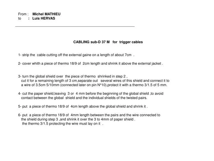
From : Michel MATHIEU to : Luis HERVAS CABLING sub-D 37 M for trigger cables 1- strip the cable cutting off the external gaine on a length of about 7cm . 2- cover whith a piece of thermo 18/9 of 2cm length and shrink it above the external jacket . 3- turn the global shield over the piece of thermo shrinked in step 2 , cut it for a remaining length of 3 cm,separate out several wires of this shield and connect it to a wire of 3.5cm 5/10mm (connected later on pin N°10),protect it with a thermo 3/1.5 of 5 mm. 4- cut the paper shield,leaving 3 or 4 mm before the beginning of the global shield ,to avoid contact between the global shield and the individual shields of the twisted pairs. 5- put a piece of thermo 18/9 of 4cm length above the global shield and shrink it . 6- put a piece of thermo 18/9 of 4mm length between the pairs and the wire connected to the shield during step 3 ,and shrink it over the 3 to 4mm of paper shield . the thermo 3/1.5 protecting the wire must lay on it .
3 4 8 6 2 5
7- for each of the 16 pairs : - cut off the aluminium shielding with a thin pair of pliers at about 6 to 10mm from the sleeve layed in step 6 ,just make a little gash finishing by hand .(A) - cut off the paper shield of the pair as shorter as possible . - put the transparent 0.8mm sleeve over the ground wire(length 5.5cm) maintaining it by turning the wire backward.(8) - put on a sleeve of thermo 3/1.5 of 5 mm at the junction of the 3 wires and the shielding , the thin transparent sleeve being inserted under the aluminium shield .shrink the thermo covering the 2 parts.(B) - cut each pair ,stripping 3mm and tinning so that the max length of each pair measured from main shield is not larger than : (C) length pair 42mm 0, 1, 14, 15 40mm 2, 3, 12, 13 38mm 4, 5, 10, 11 36mm 6, 7, 8, 9 - each pair must be identified with the noch connected at the other end. - soldering each pair maintaining the wires twisted ,put a sleeve 3/1.5 of 5mm on each wire , starting in the middle of the connector . remind to group the ground wires by 4 . - soldering the wire of the global shield on pin 10 .(put a sleeve 3/1.5 ) (D)
7B 7 D Max 7 C 7 A
8- finishing by the ground wires in 1 ,20, 19 et 37 because of the weakness , probably it will be necessary to adjust the lengths of the transparent sleeves of .8mm . 9- assembling of the case ,some glue is necessary at the end of the 2 part of the case ,install the 2 secure screw at the same time with the vise check the insulation between the case and pins 10,1,19,20,37 . 8
10- close the case with screw and bolt . thermo sleeve 18/9 : 6.5cm by connector thermo sleeve 3/1.5 : 54 x 5mm = 26 cm by connector transparente sleeve dia 0.8mm : 16 x 5cm = 80 cm by connector neopren glue fil 5/10 mm : 4.5 cm by connector 9 9