Download

1 / 20
200 likes | 235 Views
Detailed analysis of an X-Ray pinhole camera, including how beam size is measured, image processing, and resolution. Review of beam-based diagnostics and electron phase space. Learn about resolution functions and diffraction patterns.

E N D
Beam Size Measurement • Survey of beam size measurement techniques and applications. • Detailed analysis of an X-Ray pinhole camera • Description • What is actually measured? • Image processing and resolution Beam-based Diagnostics, USPAS, June 23-27, 2003, J. Safranek
Laser wire measurement, PRST-AB Shintake measurement, see Chao handbook Beam-based Diagnostics, USPAS, June 23-27, 2003, J. Safranek
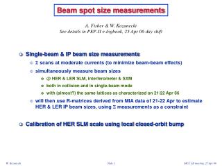
Measures of beam size • Touschek lifetime • Luminosity scan (Y. Cai, EPAC’00, p 400) • Quadrupole moment detectors (A. Jansson et al., CERN-PS, PAC’99) Beam-based Diagnostics, USPAS, June 23-27, 2003, J. Safranek
More measures BessyII pinhole array. Beam-based Diagnostics, USPAS, June 23-27, 2003, J. Safranek
Beam-beam scan, Wenninger et al., EPAC98. Beam-based Diagnostics, USPAS, June 23-27, 2003, J. Safranek
Minty and Spence Beam-based Diagnostics, USPAS, June 23-27, 2003, J. Safranek
Mitsuhashi Beam-based Diagnostics, USPAS, June 23-27, 2003, J. Safranek
7.5 m 9.3 m x-rays x-rays electrons X-Ray pinhole camera Pinhole camera on X28 dipole beamline at NSLS X-Ray Ring: mirror visible X-rays exit vacuum chamber through 250 mm Be window. pinhole: molybdenum crossed slits video camera YAG phosphor 25 mm Al foil to harden spectrum. Slit gap set to 30 mm and confirmed by measuring diffraction from HeNe laser. Slit has angles to avoid internal x-ray reflections. H2O-cooled Cu pre-absorber takes heat load. Beam-based Diagnostics, USPAS, June 23-27, 2003, J. Safranek
o L2 L1 i What is measured? The standard formula for a pinhole camera, i=(L2/L1)o, assumes that the object is radiating light equally in all directions. Synchrotron radiation is highly collimated in the direction of the electrons, so this formula does not necessarily hold. I’ll show that for a dipole beamline, it does hold in the horizontal plane, but does not in general in the vertical plane. The problem in the vertical plane is that electrons at the top of “o” (in this case the top of the electron beam) do not necessarily radiate photons that go through the pinhole, so i<(L2/L1)o. Beam-based Diagnostics, USPAS, June 23-27, 2003, J. Safranek
Review of electron phase space The on-energy electrons in a storage ring make a Gaussian in phase space. Area of e-1/2 ellipse is e. The full extent of the electron beam including energy spread is larger. Beam-based Diagnostics, USPAS, June 23-27, 2003, J. Safranek
on-energy e- Full e- ellipse with energy spread photon ellipse at source point Phase space distribution of photons at source Beam-based Diagnostics, USPAS, June 23-27, 2003, J. Safranek
Photon ellipse at source on energy electrons electrons including energy spread photons Beam-based Diagnostics, USPAS, June 23-27, 2003, J. Safranek
Measured vertical profile Coupling uncorrected Coupling corrected meas meas y’=-y/L1 The beam profile at the source point seen by the pinhole camera is the intersection of the pinhole camera acceptance, y’=-y/L1, and the photon ellipse. The electron emittance can be found with: Beam-based Diagnostics, USPAS, June 23-27, 2003, J. Safranek
sagitta electrons pinhole Measured horizontal profile In the fixed coordinates at the beamline source point, the photon ellipse sweeps across the pinhole acceptance. Integrating the changing profile gives: The ellipse sweeps across the pinhole acceptance in an arc in (x,x’). The sagitta (the change in x) is negligibly small. pinhole acceptance x’=-x/L1 The integrated profile seen by the pinhole camera is Beam-based Diagnostics, USPAS, June 23-27, 2003, J. Safranek
Resolution & image processing • Two contributions to resolution: • Pinhole diffraction. • Resolution of detector (phosphor, mirror, lens, and CCD). The two resolution functions are deconvolved from each horizontal and vertical slice. A two dimensional, tilted Gaussian is fit to the resulting profile. Example for one vertical slice. Beam-based Diagnostics, USPAS, June 23-27, 2003, J. Safranek
Calculating diffraction pattern, sum up over phases. Diffraction Even though we are dealing with X-Rays, diffraction is a significant resolution limitation. The diffraction pattern was calculated numerically as a function of pinhole dimension. For large pinholes, it looks like a geometric image of the square pinhole. For small pinholes, it looks like Fraunhofer diffraction, getting larger as the pinhole gets smaller. The pinhole size that gives the best resolution is somewhere between the Fraunhofer regime and geometric image. The diffraction pattern must be integrated over the spectrum absorbed by the YAG phosphor. Beam-based Diagnostics, USPAS, June 23-27, 2003, J. Safranek
Resolution functions All secondary maxima in the diffraction pattern wash out when integrating over the wavelength spectrum. The resolution of the detector was measured by placing a very narrow slit just in front of the phosphor. The measured image is a convolution of the real profile with the resolution functions. The data and resolution functions are sets of discreet points, so the deconvolution could be turned into a big matrix inversion. A more traditional method uses FFTs. Convolution in frequency space is simply multiplication, so deconvolution becomes division. Beam-based Diagnostics, USPAS, June 23-27, 2003, J. Safranek
Deconvolution 2. Filter high frequency noise 1. FFT 4. FFT 3. division 1. FFT Beam-based Diagnostics, USPAS, June 23-27, 2003, J. Safranek
Modulation transfer function Instead of dividing FFTs, use only amplitude part of FFT – called modulation transfer function (MTF). MTF is a common way to specify resolution. For example, this graph came with the video camera that was used for the X-Ray Ring pinhole camera. Pulnix video camera MTF Beam-based Diagnostics, USPAS, June 23-27, 2003, J. Safranek
Parting slide Numerical Recipes, Cambridge Press, is a good reference for FFTs and deconvolution. Beam-based Diagnostics, USPAS, June 23-27, 2003, J. Safranek