Download

1 / 18
180 likes | 432 Views
Development of a Lab-Scale Flame Propagation Test for Composite Fuselages. Introduction. With the increased use of non-traditional materials for modern aerospace applications, fire test methods must be continually updated and re-evaluated in order to maintain a high level of passenger safety

E N D
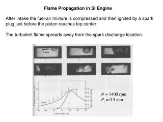
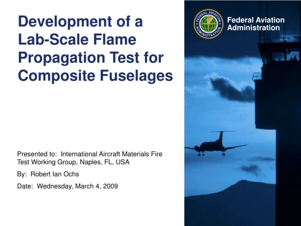
Development of a Lab-Scale Flame Propagation Test for Composite Fuselages
Introduction • With the increased use of non-traditional materials for modern aerospace applications, fire test methods must be continually updated and re-evaluated in order to maintain a high level of passenger safety • Application of fire tests to modern materials • Re-evaluation of pass/fail criteria • Introduction of new safety threats with new materials • Develop new standards or test methods to address these issues • Composite materials (carbon fiber-epoxy) are being used in places where aluminum was traditionally used • Fuselage skin • Structural members – stringers and formers • Seat frames • Fuel tanks • There is a need to evaluate the fire properties of these materials to ensure there is not a decreased level of safety
Composite Fuselage • There is a need to evaluate the fire properties of a composite fuselage • Burnthrough • Toxicity • In-flight burnthrough • Flame propagation • This objective of this study is to determine whether a composite fuselage will pose a flame propagation hazard • Identify potential scenarios where a threat may be present • Evaluate threat with full or intermediate scale test • Analyze results to determine if there is an increased risk • Use full/intermediate scale test results to develop a lab-scale test for future certification purposes
Evaluation of Flame Propagation Risk • An intermediate scale test was performed using the foam block fire source • Different configurations of the fire source, thermal acoustic insulation, and composite panel were attempted • Test results indicated that the material being evaluated did not present a flame propagation hazard • Other composites or composites of varying thicknesses may pose a threat
Development of Lab-Scale Test • Use the results from previous intermediate scale test as a baseline for a “pass” • The intermediate scale test results were used to certify that specific material for use in aircraft • The intermediate scale test will not suffice for certification, however, as it is a large test and takes time and money to perform • Certification tests must be performed when varying the material (different epoxies, thicknesses, etc.) • The lab scale test must provide the same discretion as the intermediate scale test, but be more efficient to perform • Radiant Panel Test Apparatus • The radiant panel test is very useful for evaluation flame propagation tendencies for materials • The test is a “surface” test, as radiant heat and the burner impingement are applied to the material surface • Material thickness and thermal conductivity play a large role in this test • Test parameters must be adjusted to account for composite materials of varying thicknesses (warm-up time, flame exposure time, radiant heat energy, etc.) • Task here is to determine if the radiant panel test will be useful for evaluating the flame propagation threat of composite materials
Previous Work on Composites • FAA Report DOT/FAA/AR-07/57 (Quintiere et al.) entitled “Flammability Properties of Aircraft Carbon-Fiber Structural Composite” • Investigated a material manufactured by Toray Composites America to meet Boeing Material Specification 8-276 • Key objective was to investigate the heating and burning properties of the material with various methods • Cone calorimeter • Microscale combustion calorimeter • Thermogravimetric analysis • Differential scanning calorimeter • Flame spread apparatus • Thermal conductivity apparatus • OSU and smoke chamber
Material Details • Toray Composites, BMS 8-276 • [-45, 0, 45, 90]2s 16 plies • Material is composed of carbon fibers (7µm dia.) and resin • 3.2 mm thick (0.125 in.) • Density = 1530 kg/m3 (95.5 lb/ft3) • 60% by volume carbon fibers • Resin density = 1220 kg/m3 (76 lb/ft3) • Typical char fraction of resin ~ 25%
Properties • Resin is primary fuel for reactions • Escapes the material through pores in the matrix • Heating causes material to swell as internal pressures rise • Flame jets can protrude from the material due to pressure release • Properties change as material changes in shape • Density decreases • Thermal conductivity of matrix decreases • Both flaming and non-flaming combustion can occur • Resin can produce flaming combustion • Char and carbon can smolder on the surface without flame • Thermal conductivity was measured with a home-built apparatus • Measurements were made over a range of temperatures relevant to combustion • Heat loss errors were found with the apparatus, possibly up to 20% difference • More accurate methods are needed • Despite the errors, the dependency of thermal conductivity on temperature is clear
Flame Spread Experiments • Critical heat flux was found from cone calorimeter measurements • Piloted ignition: 17.5 kW/m2 (1.5 BTU/ft2s) • Non-piloted ignition: 31.5 kW/m2 (2.8 BTU/ft2s) • Apparatus was developed in the work of Panagiotou and Quintiere • Vertically mounted specimen • Surface exposed to radiant heat is 6 x 25 cm (2.4” x 9.8”) • Pre-heat time of 4 min was used to create thermal equilibrium on sample surface (found from critical heat flux for piloted ignition) • Flame spread is only a function of heat flux for this pre-heating condition, as flame speed is dependent upon surface temperature • Key findings • Exposed heat flux of 1.25 BTU/ft2s • Pilot flame in contact entire test • Flame spread of approx 7” over 2 ½ min • Pyrolysis spread of approx 12.6” over 2 ½ min
Preliminary FAATC Measurements • BMS 8-276, 0.125” thickness, 20” x 9.5” • Radiant Panel Test, configured for 25.856(a) • 1.5 BTU/ft2s at zero position • 15 sec. pilot flame application • Result: No propagation, no after flame • 4 min. pre-heat, 30 sec. pilot flame application • Result: No propagation, no after flame • Turned sample 180°, 30 sec. pilot flame application (~6 min pre-heat) • Result: 3 sec. after flame, no propagation • Re-applied flame for 1 min • Result: 6 sec. after flame, no propagation • Damaged Panel, 15 sec. pilot flame application • 19 sec. after flame, no propagation • Pilot flame applied to rear edge of panel, 15 sec pilot flame application • Result: >15 sec. after flame, no propagation
Configuration 1 15 sec. flame application No propagation or after flame
Configuration 2 4 min. pre-heat 30 sec. flame application No propagation or after flame
Rotated sample 180°, -> ~6 min pre-heat 30 sec. flame application 3 sec. after flame no propagation Re-applied flame for 1 min 6 sec. after flame, no propagation Configuration 3&4
Configuration 5 Damaged Panel 15 sec. flame application 19 sec. after flame, no propagation
Configuration 6 Pilot flame applied to edge 15 sec. flame application >15 sec. after flame, no propagation
Summary of Initial Testing • Results: • Test conditions for 25.856(a) are not severe enough to produce any result • 4 minute pre-heat not sufficient to produce any result • ~6 minute pre-heat was able to produce short after flame • Delamination and damage to panel caused significant after flame • Application of flame to edge of panel caused significant after flame • After flame seems to behave like a candle, where fuel is drawn to the flame through the panel like a candle • Combustible gases seem to escape through the edges, which causes after flame at the edge • Sample frame should be constructed to completely block off the edges and only allow for surface to be exposed
Status • Work is in the initial phase right now • Initial work will involve tooling with the radiant panel and different composite material plaques to observe how the material behaves in this test • Vary sample size, thicknesses • Vary radiant heat and flame exposure times • Gather samples of different composite materials for intermediate and lab scale tests • Perform intermediate and lab scale tests, change test parameters such that the intermediate and lab scale results correlate
Questions or Comments? Contact: Robert Ochs DOT/FAA Tech Center Bldg. 287 Atlantic City Int’l Airport, NJ 08405 (609)-485-4651 robert.ochs@faa.gov