Download
1 / 19
190 likes | 213 Views
This project entails designing, implementing, and reviewing radiation safety measures for the LCLS accelerator. Key steps included determining hazards, beam losses analysis, and operational reviews. The shielding criteria, dose limitations, and modeling were integral aspects of the project. Documentation, reviews, and improvements were consistently incorporated in the process to maintain safety standards.

E N D
Radiation Safety and Accelerator Design and Operation at SLAC • Design • Determine hazards: prompt radiation, residual radiation, air and soil activation/contamination, etc. • Define design objectives, list operating modes • Determine beam losses and perform ray trace studies • Review • RP Peer Review • RSO and/or RSC review • Readiness review • Implementation • Installation, testing, calibration, verification of implementation, training operators, posting, develop configuration control program
(Radiation Safety … at SLAC (cont.) • Authorize • RSO Approval, PM authorization • Operation authorization (BAS, BLA, SDR/IRI/RSS, PPS and BCS procedures • Operation • Commissioning plan, inspections, monitoring • Performance Review • Review area doses, prompt survey, induced activity • Report doses to workers and public • Indentify and implement improvements
Implementation of Design Process for LCLS • LCLS Project Documentation • RP LCLS Related Documentation • Design Beam Parameters • Shielding Design Criteria • Modeling and Benchmarking • LCLS Accelerator Housing Shielding Design Features
LCLS Project Documentation • List of Related LCLS Documents • PMD 1.1-016-r0, Linac Coherent Light Source Preliminary Safety Analysis Document • GRD 1.1-001-r0, Linac Coherent Light Source Global Project Requirements • PRD 1.1-011-r1, Electron Beam Loss in the LCLS • PRD 1.9-001-r1, Physics Requirements for LCLS Conventional Facilities • ESD 1.1-310-r3, LCLS Personnel Protection System Requirements • ESD 1.1-311-r0, LCLS Beam Containment System Requirements • ESD 1.1-312, LCLS Machine Protection System Requirements • ESD 1.2-151, Changes to the Radiation Shielding in the LCLS Injector Wall Area • PSAD --- 100 mrem/yr non-rad worker, 1 rem/yr rad worker, 3 rem max credible beam event, dose to max exposed public from LCLS must be “a small fraction of” 10 mrem/yr … • GRD --- max operational beam power 5 kW, … • PRDs --- max credible beam, max continuous loss, … • ESDs --- detailed engineering specs
RP Related Documentation • List of LCLS Related Documents from RP • Elements of Radiation Safety for Accelerator Design & Operation at SLAC • RP-04-09, Radiation Safety Scheme to Protect People to Work in the LCLS-Injector Vault during LINAC and PEP-II Operation • RP-05-16, Penetration Issues in LCLS Injector Area during LINAC/PEP-II Operation • RP-05-02, Streaming calculations through LCLS injector penetrations using MARS14 Monte Carlo code and comparison with analytical methods • RP-05-15, Shielding and BCS Requirements for Phase One of LCLS Injector Operation • RP-05-07, MARS15 Simulation for the LCLS Dump Line • RP-05-08, Residual Activity Simulation for the LCLS Beam Dump by Mars15 • RP-06-03, Shielding Design Study for the LCLS Beam Dump Line • RP-05-14, Shielding Requirements for LCLS Front End Enclosure, White Beam Optics Room and Near Hall Hutches • RP-06-XX draft, FLUKA Calculations for LCLS Mazes and Penetrations
Beam Parameters • Max values for purpose of shielding design * Design beam max is 1.6 kW, shielding is designed for 5 kW
Shielding Design Criteria • Normal mode of operation • The integrated dose equivalent outside the BTH must not exceed 0.01 Sv/yr (1 rem/yr) • The integrated dose equivalent to personnel working inside and around the experimental hutch shielding barriers should not exceed 1 mSv/yr (100 mrem/yr) • Maximum Credible Beam • The dose equivalent-rate is limited to less than 0.25 Sv/h (25 rem/h), and integrated dose equivalent of less than 0.03 Sv (3 rem)
Modeling and Benchmarking • MARS15 Simulation of LCLS Dumpline 14.1 GeV electrons Bending into the beam dump Secondary particle shower By beam loss at first bending magnet
Beam Dump Hall Modeling • Prompt dose Vertical distributions of prompt dose rate for beam loss at first bending magnet entrance at 1 mrad (14.1 GeV-30W)
Beam Dump Hall Modeling (cont.) • Residual activity Below 0.01 mSv/h at top concrete Residual Dose Rate (30-day operation 1-day cooling)
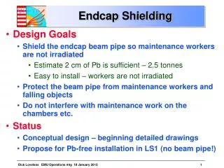
FFTB LCLS Accelerator Housing Shielding Design Features • BTH walls, ceilings, entrance mazes, and penetrations are design to meet RP specifications. • LCLS (5 kW, 15 GeV) walls much thicker than FFTB (2.4 kW, 50 GeV) 4+ ft 6 ft Ground Level
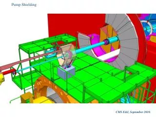
BTH - Support Buildings • 6 ft ceiling for occupied areas • Note penetration design for cables
Beam Dump Hall Plan View Entry Maze Covered trenches Electron beam descending to pit
Beam Dump Hall Elevation View Muon steel • Elevation view Dump Pit Lid (Steel) xrays electrons trench Dump Pit
Beam Dump Coverage • Example section taken through center of beam dump • Result after many iterations between architect, structural engineer and RP Parking
Beam Dump Steel Shielding • Very heavily shielded • ≈ 400 tons steel, not including overage or FEE/NEH wall. • Mixture of existing weakly radioactive and newly purchased steel. SLAC to provide all steel. • Installed while Beam Dump Hall is open • Beam dump is in the cut and cover section • Removable parts of the lids allow access to pit • Requires downtime
LCLS Shielding Design Summary • SLAC radiation safety and accelerator design process has been implemented for LCLS • Design criteria is well established • Most modeling and analysis is done • Construction design incorporates shielding required to meet the design criteria.