Download
1 / 19
200 likes | 456 Views
Radiation Shielding Design of NSLS2. P.K. Job Conventional Facilities Advisory Committee Review May 8 , 2007. Preliminary Shielding Design Documents. 1. Linac, NSLS II- TN 12 2. Booster & Storage Ring, NSLS II – TN 13 3. Storage Ring Supplemental Shielding – TN 21

E N D
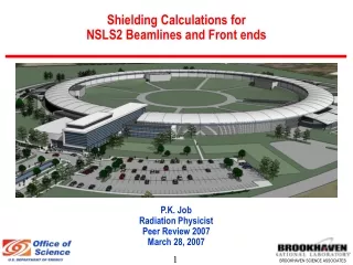
Radiation Shielding Design of NSLS2 P.K. Job Conventional Facilities Advisory Committee Review May 8 , 2007
Preliminary Shielding Design Documents 1. Linac, NSLS II- TN 12 2. Booster & Storage Ring, NSLS II – TN 13 3. Storage Ring Supplemental Shielding – TN 21 4. Beamlines and Front Ends, NSLS II – TN 14 5. Ray Tracing Standards, NSLS II – TN 20 6. Activation Analysis, NSLS II – TN 15 & 16
Radiation Safety Review • March 27 – 28, 2007 • Membership • S. Rokni (Chair) – SLAC • R. Donahue – ALS • P. Berkvens – ESRF • D. Beavis – BNL • C. Schaefer - BNL
Radiation Safety Review • Committee reviewed: • Shielding methodology & assumptions • Interlocks, Critical Devices, and Area Radiation Monitoring plans. • Committee concluded: “Given the status of the project, the design of the bulk shielding of the accelerator complex is well developed and is based on sound principles and reasonable assumptions. “
Desired Shielding Outcome • Compliance with DOE Orders, Part 835, and BNL Administrative Controls • < 25 mRem/year (.25 mSv) on-site to non-NSLS-II personnel; < 5 mrem/year (0.05 mSv) at site boundary • Radiation exposure to users and staff ALARA – an administrative control level of 100 mRem/year (1 mSv) is desired • We plan to achieve this through shielding and engineering controls; & supplemental administrative controls • Based on current experience, we expect annual radiation exposures < < 100 mRem/year (1 mSv) to NSLS staff and users • After verification, we expect short-term visitors will not be required to have dosimeters routinely
Shielding Policy • Accelerator and beam line enclosures will be shielded to reduce exposure at the exterior surface of the shield during typical operation to 0.25 mRem/hr (2.5 uSv) in normally occupied areas to limit the maximum exposure to 500 mrem/year (5 mSv) (assuming 2000 hours occupancy). • The storage ring outer wall will be shielded to 0.5 mRem/hr (5 uSv/hr) in direct contact with exterior; no full-time occupancy is expected or will be permitted within 1 meter of wall. • This policy satisfies DOE Design Goals identified in 10 CFR 835.1002
Radiation Sources Consideredfor calculations • Bremsstrahlung (High Energy Photons) • Bremsstrahlung produced Neutrons • Synchrotron Radiation (Low Energy x-rays)
Dose Equivalent Factors used for Calculations(Thick Target Approximation)
Accelerator Operating Conditions used in Calculations • Linac • 200 MeV • 20 nA • Booster • 3.5 GeV • 15 nC per pulse • 1 pulse / minute (typical operation) • 1 hz operation for 500 hours per year considered • Storage Ring • 3.6 GeV • 500 mA
Beam Loss Assumptions during Normal Operations • Linac – 1% distributed loss at 200 MeV • Linac to Booster injection efficiency – 50% • Booster losses – 2% loss at any point at 3.5 GeV • Booster to storage ring injection efficiency – 80% • Non-injection region – 10% of stored beam losses at any point • Stops in linac and booster designed for 100% loss at 1 hz
Booster Bulk Shielding Estimates1 1 The Inboard and Outboard walls are at 1 m and the roof at 2 m from the beam 2 Supplemental lead shielding will be required around injection septum for 1 hz operation Booster shielding still in progress as adjacent occupancies are under discussion.
LINAC - Credible Radiation Incidents • 100 % of maximum accelerated beam is lost at some location in the linac enclosure, (20 nC/s is continuously lost) Dose Rate = 37.5 mRem/h (0.37 mSv/h) (at the exterior of shield on contact) • 100 %injected beam to the booster is continuously lost at the linac-booster injection septum at 1 Hz. Dose Rate = 30 mRem/h (0.3 mSv/h) Mitigation/ control to prevent significant exposure • Area Radiation Monitors with beam shut off capability • Beam current monitors in the LINAC • Additional supplementary shielding at the septum/stop (lead/poly) • Operating procedures for operators during injection
Storage Ring (Credible Radiation Incidents) • 100 % injected beam from the booster to storage ring is lost at any location in the storage ring (15 nC/s is continuously lost at some location other than injection region) Dose Rate = 300 mRem/h (3 mSv/h) (at the exterior of the experimental floor wall on contact) • 100 % injected beam from the booster to storage ring is lost at any beamline front end due the shorting of a bending magnet (15 nC/s is continuously lost at a front end component) Dose Rate = ~ 500 mRem/h (4 mSv/h) (at the exterior of the ratchet wall ~ 0.5 m from the FE) (peak bremsstrahlung shielded with shadow shields) • 100% of stored beam is lost at a point - ~ 8 mRem (0.08 mSv) Mitigation/controls to prevent significant exposure • Area Radiation Monitors with beam shut off capability • Beam loss monitors inside the Storage Ring • Additional Supplementary Shielding (Shadow Shields) • Operating procedures for operators defining actions during injection