Download
1 / 31
320 likes | 529 Views
A Low-Power Architecture for Sensor Nodes. DEUS EX MACHINA: Octav Chipara Paul Gross Harri Thorvaldsson. Wireless Sensor Networks. Wireless sensor motes sense temperature, humidity etc., transmit and route data

E N D
A Low-Power Architecture for Sensor Nodes DEUS EX MACHINA: Octav Chipara Paul Gross Harri Thorvaldsson
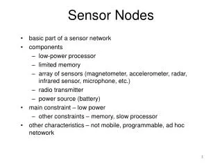
Wireless Sensor Networks • Wireless sensor motes sense temperature, humidity etc., transmit and route data • Very limited: e.g. 4KB RAM, 64KB Flash, 40-250Kbps radios, 8/16 bit microcontrollers (MCUs) • Need to run for long time (month, years!) on batteries, i.e. two AA batteries. Mica2 Telos
Workload = multiple periodic queries running concurrently, e.g. Data flows from leaves to wired base station at top Alternating low (waiting) and high-activity (working) periods Data aggregation and processing can be MCU-intensive Monitoring application characteristics SELECT AVG(humidity) AVG(temp) FROM sensors SAMPLE PERIOD 1s
Problem: MCU and radio waste power 1: Non-power aware system Power Time Activity
General solution: powersaving modes 2: Power-aware: sleep while idling Sleep periods Power Time
Further chipping away at power 3: Sleep Deeper: gating, voltage scaling … Power Time
Our enhancements, part A 4: Sleep Longer, exploiting periodicity Power Time
Our enhancements, part B 5: Work while sleeping, via specilized chip Power Time
Background: Essence of ESSAT Expected time of first child packet Actual time Send to parent Period n Time Read sensor Delay Period n+1 Time Shift
Saving power via periodic scheduling • Old: MCU is boss, waits for interrupts, controls the power level of other devices • Interrupt-ready sleeping MCU quite power-hungry (5-600A) • Assume nothing devices turned on longer than needed MCU
Saving power via periodic, cont. • New: Power Management Unit (PMU) is boss, runs a periodic task schedule • Sets device powerstates, including MCU (to deepest sleep) • Maximizes sleep times and minimizes transition penalties • PMU: extremely small, simple and power-efficient MCU PMU
Deployment target: on-board CPLDs! • CPLDs are very energy efficient • CPLDs can be reprogrammed in-circuit • A modular PMU allows per application customization and selection of features, yielding a smaller circuit. • Plug in aggregation functions, filters • Interface with different devices, memories and buses. • Adjust ISA to application needs
Software/hardware co-design • Hardware: • New sensor node architecture • With specialized chip for power management, query processing, I/O • Uses periodic ESSAT-style scheduling: • Sleep long and deep without transition penalties • Dynamically adapt to changing workloads • Supports energy-hungry MCUs SELECT AVG(humidity) AVG(temp) FROM sensors SAMPLE PERIOD 1s • Software: • Integration with TinyOS (mote OS kit) • Design a library for taking advantage of the new hardware architecture • Dynamic PMU code generation from query definition
Evaluation Approach: Micro and macro benchmarks • Hardware: VHDL / XST • Chip-level simulation • Show it fits on a CPLD • Show it works • Estimate power (using XPower) SELECT AVG(humidity) AVG(temp) FROM sensors SAMPLE PERIOD 1s • Software: TinyOS / AVRORA • Mote system-level simulation • Estimate energy savings • Investigate trade-offs between different PMU feature sets
First design: PMU-1 • PMU is simple, potential for energy savings over MCU • Schedule loaded into SRAM by MCU • Tiny programs (e.g. 32 instructions) in SRAM • PC increments through instructions in memory • Instructions turn on/off devices, with delay following • Counter counts down cycles of delay, returns control to PC • Comparator used in waiting for interrupt on return instructions
PMU-1 ISA • PMU-1 has three 16-bit instructions (8 bits instruction, 8 bits delay after instruction) • Set device power state (SWITCH) • Jump to instruction (GOSUB) • Return from last jump (RETI) • Delay encoded as 2exp + add*2(exp-3)
Example Waveform • Sample Program • Switches 3 devices on with delays • Jumps • Switches 3 devices off with delays • Returns, jumps back to beginning
Simulate PMU-1 on purely cyclical schedules Analyze simulation with XPower assuming: Coolrunner XPLA3 CPLD Lowest voltage supported PMU Power estimation
PMU-1 Implementation • Implemented PMU-1 on Spartan-3 test board • LEDs “represent” devices turning on/off • Special thanks to David Zar Program: SWITCH 1 0 0 1 SWITCH 1 3 0 1 SWITCH 0 0 0 0 SWITCH 0 3 0 0 GOSUB 0 0 2
Second design: PMU-2 • Assume contemporary and near-future hardware • More autonomous devices (radios, sensors etc.), communicating over common buses (SPI, I2C etc.) • Design goal: handle routine tasks while MCU sleeps. • Runs ESSAT periodic scheduling of communication. • Move data between devices (serve as DMA engine) • Receive and send packets, sense and aggregate data. • Needs to access buses, RAM, acquire packet header and payload data, aggregate, assemble and transmit packet, adjust query scheduling …
PMU-2 Design • Task table, co-operative task-switching • Device table: dynamic powerstate conflict resolution • Main ISA instructions: • PEEK / POKE: read / write a byte from / to a bus. • LOAD / STORE: load a variable into the accumulator • ADD / SUB: add or subtract from the accumulator • JMP(C) / GOSUB(C) / RET: (conditionally) jump, jump and store return address and jump to return address • S{L/G}E: compare to accumulator and set condition • WAIT: wait for a timeout or interrupt • “System software” Too Complex
PMU-3 • New design goal: run a PMU-1 like MCU “precooked” schedule but be able to receive, aggregate and transmit packets by itself (as long as no problems) • Simpler, less general, more focused design • Has PMU-1-like schedule programs (8-bit ISA) • SLEEP, GOSUB, RET: wait, subroutine jumps and returns • WRITE: write immediate to bus, to set powerstate or give command to sensor or radio. • RDADDn: read data value from sensor n via bus • Precooked schedule no tasks, no need for dynamic powerstate conflict resolution, no tables
PMU-3 • Has packet handler subroutines, invoked on arrival of a packet • Dispatched on a query ID byte in packet header • Instructions to read bytes from radio and add to aggregate data values in a per-query memory buffer • Buffer has exact same layout as data in packet • RDADD, RDMAX, RDMIN Packet 4 12 21 3 Mem: 1 4 5 1 RDADD
PMU-3 • Has packet handler subroutines, invoked on arrival of a packet • Dispatched on a query ID byte in packet header • Instructions to read bytes from radio and add to aggregate data values in a per-query memory buffer • Buffer has exact same layout as data in packet • RDADD, RDMAX, RDMIN Packet 4 12 21 3 Mem: 5 4 5 1 RDADD
PMU-3 • Has packet handler subroutines, invoked on arrival of a packet • Dispatched on a query ID byte in packet header • Instructions to read bytes from radio and add to aggregate data values in a per-query memory buffer • Buffer has exact same layout as data in packet • RDADD, RDMAX, RDMIN Packet 4 12 21 3 Mem: 5 4 5 1 RDADD
PMU-3 • Dynamic state per query: • Pointer in memory • Number of child packets received • Static state (from program text) per query: • Query ID • Memory buffer address • Packet handler address • Global static state • Mote ID • Number of queries • Number of children • Timeout for waiting for child packets
System Integration Sensors ADC MCU PMU CC1000 Spi/PortD Spi/Conf Spi/Conf Spi/Conf PMU Code: … SWITCH HumiditySensor ON GoSub ReadHumiditySenor SWITCH TempSensor ON GoSub ReadTempSenor SWITCH Radio ON GoSub AggregateQ1 SWITCH Radio OFF … Query Definition: SELECT AVG(humidity) AVG(temp) FROM sensors SAMPLE PERIOD 1s
System Integration (2) • TinyOS: • Implement the PMU code generator in TinyOS • Modify the drivers for the CC1000 radio • Write drivers for reading/writing from PMU • AVRORA: • Hardware platform simulator: • Atmel MCU (cycle accurate) • SPI buses • Analog/Digital converters • AVRORA estimates energy consumption on the platform • Use XPower numbers for power-consumption of PMU
System Level Experiments • Goal: Track the improvement in energy savings for different PMU architectures in single and multi-hop environments. • Baseline 1: TinyOS interrupt-driven power management • Baseline 2: Periodic power management • Experiment 1: Periodic power management + PMU1 • Experiment 2: Periodic power management + PMU3 • Status: • Experiment 1: May be run