Download
1 / 1
30 likes | 249 Views
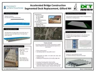
Accelerated Bridge Construction Bunker Creek Bridge, Durham NH. Bunker Creek. NEXT D Beams. Columns. Drilled Shaft 1 ft outside of current roadway. Cast in place with early high strength concrete.

E N D
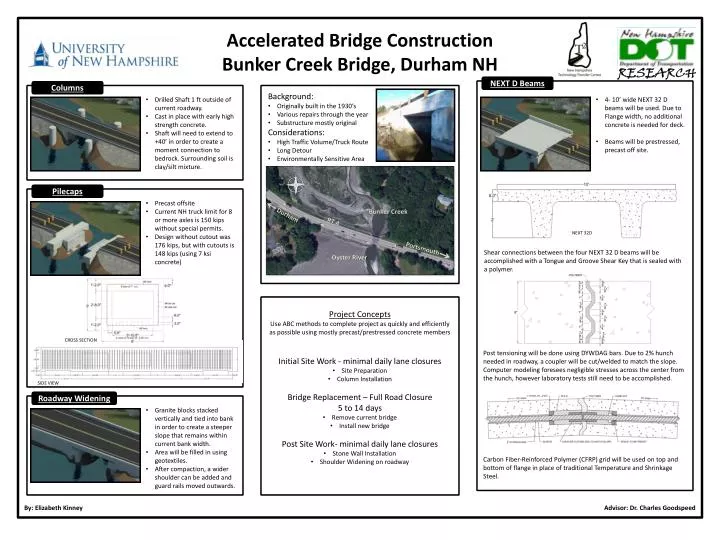
Accelerated Bridge Construction Bunker Creek Bridge, Durham NH Bunker Creek NEXT D Beams Columns • Drilled Shaft 1 ft outside of current roadway. • Cast in place with early high strength concrete. • Shaft will need to extend to +40’ in order to create a moment connection to bedrock. Surrounding soil is clay/silt mixture. • 4- 10’ wide NEXT 32 D beams will be used. Due to Flange width, no additional concrete is needed for deck. • Beams will be prestressed, precast off site. Oyster River • Background: • Originally built in the 1930’s • Various repairs through the year • Substructure mostly original • Considerations: • High Traffic Volume/Truck Route • Long Detour • Environmentally Sensitive Area Project Concepts Use ABC methods to complete project as quickly and efficiently as possible using mostly precast/prestressed concrete members Pilecaps • Precast offsite • Current NH truck limit for 8 or more axles is 150 kips without special permits. • Design without cutout was 176 kips, but with cutouts is 148 kips (using 7 ksi concrete) Durham NEXT 32D RT 4 Portsmouth Shear connections between the four NEXT 32 D beams will be accomplished with a Tongue and Groove Shear Key that is sealed with a polymer. CROSS SECTION Post tensioning will be done using DYWDAG bars. Due to 2% hunch needed in roadway, a coupler will be cut/welded to match the slope. Computer modeling foresees negligible stresses across the center from the hunch, however laboratory tests still need to be accomplished. • Initial Site Work - minimal daily lane closures • Site Preparation • Column Installation • Bridge Replacement – Full Road Closure • 5 to 14 days • Remove current bridge • Install new bridge • Post Site Work- minimal daily lane closures • Stone Wall Installation • Shoulder Widening on roadway SIDE VIEW Roadway Widening • Granite blocks stacked vertically and tied into bank in order to create a steeper slope that remains within current bank width. • Area will be filled in using geotextiles. • After compaction, a wider shoulder can be added and guard rails moved outwards. Carbon Fiber-Reinforced Polymer (CFRP) grid will be used on top and bottom of flange in place of traditional Temperature and Shrinkage Steel. By: Elizabeth Kinney Advisor: Dr. Charles Goodspeed