Download
1 / 57
650 likes | 1.06k Views
CHAPTER. Electrical Components. 4. Instructor Name: (Your Name ). Learning Objectives. Describe the components that make up a truck wiring harness Repair a damaged section of wire Determine the correct wire gauge to be used based on the amperage and length of the conductor

E N D
CHAPTER Electrical Components 4 Instructor Name:(Your Name)
Learning Objectives • Describe the components that make up a truck wiring harness • Repair a damaged section of wire • Determine the correct wire gauge to be used based on the amperage and length of the conductor • Describe the different types of electrical switches using terms such as poles, throws, normally open, and momentary contact
Learning Objectives (continued) • Use a voltmeter to determine if a switch is open, closed, or defective • Define the function of each terminal of a standard ISO relay • Troubleshoot a circuit controlled by a relay and list the most likely failures of a relay • Explain how circuit protection devices (CPD’s) operate and the importance of replacing a CPD with the rating specified by the OEM
Learning Objectives (continued) • Use a voltmeter to determine if a CPD is open • Locate an open circuit and shorted to ground circuit, using wiring schematics and electric test tools
Wiring Harnesses • A wiring harness is a modularized section of wires designed to be connected to electrical components and other wiring harnesses • Connectors are interlocking devices that permit connections to electrical components or wiring harnesses • Terminals are electrically conductive pins (male) and sockets (female) that provide electrical connections between two connectors
Typical Wiring Harness Figure 4-1 Typical wiring harness.
Tech Tip You may find that one or more terminals may be missing in a multi-terminal connector that has been exposed to road salt mixed with water, while the other terminal may only have a small amount of corrosion. Terminal in the connectors supplied with constant battery power can dissolve in a brief amount of time when exposed to salt water.
Wire Details • Stranded wire, wire made up of several smaller-diameter wires, is the most common found in use in trucks • Wire diameter is most commonly measured by the American Wire Gauge (AWG) or International Organization Standardization (ISO) • Wire size is the actual conductor not including the insulator
Stranded Wire Figure 4-2 Stranded wire.
Wire Details (continued) • The smaller the AWG number gets the larger the wire diameter gets • Cable is often used to describe large-diameter wires • ISO metric wiring indicates the cross- sectional area of the wire in mm² • The larger the ISO rating the larger the wire diameter
AWG and ISO Wire Sizes Figure 4-3 AWG and metric ISO wire sizes.
Wire Details (continued) • The resistance of a wire decreases as the diameter increases • The resistance of a wire increases as the length of the wire increases • Because resistance increases with length, it may be necessary to increase the wire gauge for loads that are a long distance for the voltage source • Automobiles often use polyvinyl chloride material as an insulator • Most insulators are color coded to provide circuit identification on the vehicle
Chassis Ground • Current needs a path from the positive terminal of the battery through electrical device and back to the negative terminal of the battery • The negative terminal of the battery is connected to the steel frame rails providing the return path • When the negative battery terminal is connected to the frame rail it is said to have a negative ground • With a negative ground system, only a positive wire is needed from the battery
Typical Chassis Ground Symbols Figure 4-6 Chassis or frame ground symbols: a low-resistance circuit is assumed.
Flexible Conduit Protects Wire Insulation from Abrasion Figure 4-7 Flexible conduit protects wire insulation from abrasion.
Wiring Harness Repairing • Standard compress or crimp type butt connectors are fast • Heat-shrinkable butt connectors are preferable • Terminals come in three color coded sizes; red, blue, and yellow • Soldering wires, then covering with a heat shrinkable tubing, is the preferred method for repairing if time allows • Plastic or electricians tape is not acceptable for sealing wiring repairs outside the cab
Crimp-Type Butt Connectors With Heat-Shrinkable Insulation Figure 4-8 Crimp-type butt connectors with heat-shrinkable insulation.
Connectors and Terminals • Molded connectors contain terminals molded in a rubber or soft plastic material. • Molded terminals are often designed to mate with a specific device or component. • Hard shell connectors contain 1 to 80 terminals. Hard shell connectors are used to provide interconnections between wiring harnesses and electronic control modules.
Sealed Connectors Figure 4-12 Individual wire seals installed before crimping terminals to wire end. Figure 4-11 Hard-shell connector body. Figure 4-13 Multi-wire connector seal.
Crimping Terminals Figure 4-14 Terminal crimping tool. Figure 4-15 Wire end and terminal before and after crimping operation.
Installing Terminals Figure 4-17 Wire with terminal and individual seal is inserted into connector body. Figure 4-19 Pull-to-seat terminals: terminal is crimped to wire end after inserting wire end into connector body and seal.
Installing Terminals (continued) Figure 4-20 Pulling the terminal to seat into place in the connector body after terminal is crimped to wire end. Figure 4-21 Special terminal extracting tools.
Switches • When a switch is on it is closed • When a switch is off it is open • The two pieces of a switch that actually make or break current are known as contacts • Poles describe the number of input terminal a switch has • Throw describes the number of positions a switch can be moved to and still complete a circuit • The terms pole and throw are used together to describe the basic functionality of a switch
Knife Switch Figure 4-22 Knife switch.
Switch Types Figure 4-23 Single-Pole Single-Throw (SPST) Figure 4-24 Double-Pole Single-Throw (DPST) Figure 4-25 Single-Pole Double-Throw (SPDT)
Switches (continued) • Latching switches remain in the position they are placed in • Momentary contact switches open or close the circuit as long as the user holds the switch • The normal state of a momentary switch is the contact position when the switch is not activated • NC = normally closed • NO = normally open
Switch Troubleshooting Figure 4-30 High resistance switch. Figure 4-31 Open circuit before switch. Figure 4-32 Open circuit after switch.
Relay Components Figure 4-33 Relay components.
Terminal Designation and Function of a ISO or DIN Relay • 85 and 86 – Coil terminal, normally 50Ω to 100Ω of resistance between them • 30 – Common terminal. Normally connected to power source. • 87 – Normally open terminal. When the relay is energized the 30 and 87 terminal will close • 87A – Normally closed terminal. When the relay is energized the 30 and 87A terminal will open
ISO or DIN Relay Terminals and Footprint Figure 4-34 Common relay terminals and footprint.
Typical Relay Contact Schematics Figure 4-35 Typical relay contact schematics.
Larger Relays Figure 4-38 Components of a magnetic (mag) switch.
Circuit Protection Devices • Circuit protection devices (CPD) primary purpose in a truck is to protect the wiring harness • CPD’s include fuses, circuit breakers, fusible links, and positive coefficient devices • CPD’s allow current flow up to the current rating then melt and open the circuit • OEM’s select current rating based on the smallest wire in the circuit being protected
Circuit Protection Devices • Any additional wiring added to a truck should be protected by a CPD • Never replace a wire with a wire of smaller diameter • Some CPD’s are designed to open more slowly or more quickly then others to permit inrush current • Common causes for excessive current flow in a circuit are excess current drawing devices or a short to ground • Always replace a CPD with the OEM recommended rating
Typical Automotive Fuses Figure 4-41 Blown or Open Fuses Figure 4-42 Automotive Type Fuses
Circuit Breakers • Circuit breakers are a form of CPD’s • Circuit breakers have thin bi-metal strips that when heated bend or snap and open the circuit • An open circuit breaker is considered tripped • When the circuit breaker cools it resets • There are three SAE classifications of circuit breakers; Type I, II and III
Circuit Breakers (continued) • Type I circuit breakers automatically reset after they cool down • Type II circuit breakers automatically reset after the cause of the excess current draw is no longer present • Type III circuit breakers manually reset after the excess current draw is no longer present and the bimetal strip cools
Type I, II, And III Circuit Breakers Figure 4-48 Type I Figure 4-50 Type III (A) and Type II (B).
Application of Circuit Protection Devices Figure 4-53 Figure 4-54 One fuse protecting several circuits. One fuse for each parallel branch.
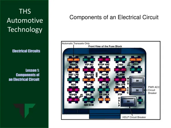
Typical Truck CPD Layout Figure 4-55 Typical truck CPD layout.
Terminology for Wiring Problems • Open circuit - a circuit with high or infinite circuit resistance, which results in reduced or interrupted current flow in the circuit • Short to ground – occurs when the conductor in a circuit has an unwanted contact with ground • Short to battery positive - occurs when the conductor in a circuit has an unwanted contact with positive voltage source • Wire to wire short – Occurs when the conductor in a circuit has unwanted contact with another wire
Types of Wiring Defects Figure 4-57 Types of wiring defects: (A) Open circuit, (B) short to ground, (C) short to battery positive, (D) wire to wire short.
Basic Electrical / Electronic Diagnostic Procedure Flowchart Figure 4-48 Diagnostic flowchart.
Common Wiring Diagram Schematic Symbols Figure 4-59 Common wiring diagram schematic symbols.
Fuse Wiring Diagram For Heated Mirrors and Back-up Lamps Figure 4-60 Fuse wiring diagram indicating fuse F5 supplies the mirror heat and back-up lamp circuits.
Using Peak Hold to Find Intermittent Short Figure 4-63 Using peak hold with DMM ohmmeter to find intermittent short.
Test Light Indicating Presence of Voltage Figure 4-65 Test light indicating presence of voltage.
Normal Voltage Readings Figure 4-66 Circuit with no defects, open switch and closed switch.
Summary • Truck wiring is divided into a series of sections called harnesses. Harnesses are mated using connectors. Connectors contain terminals the provide the electrical contact between sections of wire. • Wire diameter for North American - built trucks is typically defined by the AWG number. The smaller AWG number, the larger the wire diameter.