Download
1 / 24
270 likes | 728 Views
HYDRAULICS & PNEUMATICS. Basic Concepts FluidSIM-H. Presented by: Dr. Abootorabi. Energy. Potential energy: W=m.g.h Press with elevated reservoir:. Energy. Pressure energy: W=p. Δ V. Energy. Motion energy:. Thermal energy:. Power. Power. Efficiency.

E N D
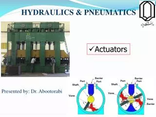
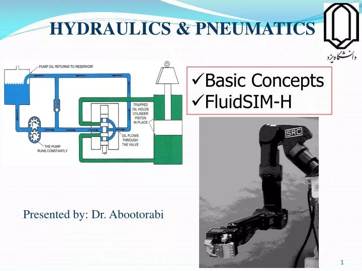
HYDRAULICS & PNEUMATICS • Basic Concepts • FluidSIM-H Presented by: Dr. Abootorabi
Energy • Potential energy: W=m.g.h Press with elevated reservoir:
Energy • Pressure energy: W=p.ΔV
Energy • Motion energy: • Thermal energy:
Mass Density = Weight Volume Specific weight = Volume = W m = N.m-3 kg.m-3 V V = g [N. m-3] Physical Properties of Hydraulic Fluids Specific Weight • Also known as unit weight, is the weight per unit volume of a material. Specific weight – Density relationship: W = mg
Density of the oil [kg/m3] oil oil SGoil = = water water Density of water [kg/m3] 9800 N/m3 1000 kg/m3 Specific Gravity (SG) • Specific gravity is a dimensionless unit defined as the specific weight of the fluid divided by the specific weight of water. Specific weight of the oil [N/m3]
p g Pressure Head • It represents the height of a fluid column that produces the static pressure. H = 1 ft 0.433 psi In other words, due to its weight, a 1-ft column of water develops at its base a pressure of 0.433 psi. The 1-ft height of water is commonly called a pressure head. Pressure - head relationship: p = H Pressure - force relationship: p = F / A
Flow rates are frequently specified in units of liters per second (Lps) or liters per minute (Lpm). 1m3 = 1000 L The Continuity Equation for Hydraulic Systems Use of Volume Flow Rate Q Q1(m3/s) = A1(m2) 1(m/s) = A2 2 = Q2
A2 1 (/4) D22 = = 2 (/4) D12 A1 2 D2 ( ) 1 = D1 2 The Continuity Equation for Hydraulic Systems • Q is the volume flow rate ( volume of fluid passing a given station per unit time). • Hence, for hydraulic systems, the volume flow rate is also constant in a pipe line. The continuity equation for hydraulic systems can be rewritten as follows: Continuity equation for hydraulic system Where D1 and D2 are the pipe diameters at stations 1 and 2, respectively. The final result is: This equation shows the smaller the pipe size, the greater the velocity.
Q Rod p F Load Barrel Piston Hydraulic Power Hydraulic Cylinder • Hydraulic power is thepower delivered by a hydraulic fluid to a load-driving device such as hydraulic cylinder. • Let’s analyze the hydraulic cylinder (above figure) by developing equations that will allow us to answer the following 3 questions:
Hydraulic Power Hydraulic Cylinder QUESTIONS • How do we determine how large a piston diameter is required for the cylinder? • What is the pump flow rate required to drive the cylinder through its stroke in a specific time? • How much hydraulic horsepower does the fluid deliver to the cylinder?
Q Rod Load is known from the application p F Load Pressure is established based on the pump design Barrel Fload Piston A = p ANSWER 1 – Piston Size • Pressure p acts on the area of the piston to produce the force required to overcome the load:
Piston area Piston velocity S A ANSWER 2 – Pump Flow Rate Q [m3/s] = A [m2] × [m/s] The larger the piston area and velocity, the greater must be the pump flow rate. Volume displacement VD of the hydraulic cylinder = A X S Q = VD / t = (A X S) / t = A X Pump flow rate in a specific time Piston velocity
ANSWER 3 – Hydraulic power = Force X Distance Energy = F X S Power = = p A X S Time p A S = t p A = or Pa p Q = Hydraulic power (W) = p [N/m2] X Q [m3/s] Hydraulic power (kW) = (p [bar] X Q [lit/min])/600
Mechanical Power • The mechanical output power delivered by a hydraulic motor: T (N.m) X (rad/sec) Power (W) = If RPM is given , must change to rad/sec by X 2/60