Download
1 / 32
320 likes | 340 Views
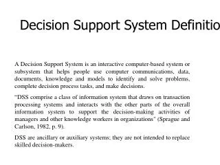
Our mission is to provide continuous area coverage for advertising in South Florida using a UAV system. Major design requirements include customer attributes, engineering specs, and concept evaluation for LED screens and advertising options.

E N D
Team 5 System Definition Review Robert Aungst Chris Chown Matthew Gray Adrian Mazzarella Brian Boyer Nick Gohn Charley Hancock Matt Schmitt
Outline of Presentation • Concept of Operations • Design Requirements • Concept Selection • Payload Analysis • Constraint Analysis • Sizing Studies • Final Concept
Mission Statement • Our mission is to provide an innovative advertising medium through the use of an Unmanned Aerial System (UAS)
Concept of Operations • Continuous area coverage of South Florida metropolitan areas and beaches for advertising purposes • Advertisements change based on location and circumstance • Targeted advertising for specific areas • e.g. advertising Best Buy near Circuit City locations • Large, fuselage mounted LED screens will deliver adverts • Business will be developed around this new technology
Concept of Operations Operations based at Sebring Regional Airport, serving 3 high population areas Continuous area coverage of city for 18 hrs (6am to 12am) 3 missions total with 6 hour loiter each Seven planes needed for 3 city operations with 1 spare Coverage area map:
Schedule Generation Application 13 destination choices within 175 nm Sort schedule by Time, Destination, Plane, & Action Allows detailed operations planning Concept of Operations
Major Design Requirements • Customer Attributes • Advertisement visibility is paramount in order to meet customer’s needs • Must maintain a loiter speed which allows the public to retain the content of advertisements • For a successful venture, these two requirements must be clearly met in order to provide a superior service to the customer • Engineering Requirements • Screen dimensions: 7.42’ x 30’ (each) • Loiter Speed: 60 kts • Loiter Endurance: 6 hrs
4 Concepts Must Be Evaluated 2 LED Screens Under Wings 2 LED Screens on Fuselage 1 Banner 1 LED Screen on Fuselage
Payload • Component Selection and Sizing • Screen • Engine • Generator • Camera • Parachute
Screen Two High Intensity LED Screens 7.42 ft X 30 ft Viewable up to 1500 ft 500 lbs installed (each) $120k cost (each) Power Consumption 3.9 kw/5.2 hp, each Daytime Viewable Brightness: 6500 cd/m² Dynamic Display 60 fps video/text Weatherproof
Engine and Propeller Considerations • Honeywell TPE-331 Turboprop • Over 14,000 Manufactured • 20+ Variants • HP ≈ 500-1700 • SFC ≈ 0.55 • Weight ≈ 350-400 lbs • P&W PT6A Turboprop • Over 36,000 Manufactured • 50+ Variants • HP ≈ 500–1900 • SFC ≈ 0.60 • Weight ≈ 300-400 lbs • Many 4000–8000 lb GTOW Single Engine Applications • Propellers • Hartzell 3,4 Blade • McCauley 3,4,5 Blade • Diameter ≈ 82-110 in • Weight ≈ 50-150 lbs • Variable Pitch • Aluminum • ηp ≈ 0.77 • Cessna Caravan 208
Generator Used to power screens, avionics, etc Screen requirements: 12.89 kW (17.3 hp) AC 30% efficiency AC-DC-DC conversion. 12.89 kW/screen X 2 screens X 30% = 7.7 kW DC (10.3 hp) Options: Gas-powered APU + Generates excess power, provides emergency backup power - Uses considerable fuel, heavy External propeller-powered APU + Provides emergency backup power - Increases drag, adds complexity Electric generator driven by accessory gearbox + Simple, supplied and designed by engine manufacturer - Increases engine cost, no emergency power
Camera • Micropilot MP-Dayview • High resolution CCD camera • Designed for UAV applications • Roll and elevation control via joystick • Two-axis gimbal for image stabilization • 25x optical zoom • Weight: 2 lb
Parachute Recovery System • Ballistic Recovery Systems • Largest current application: • Cessna 182 (3100 lb GTOW) • Cost: $17,445 • System Weight: 85 lbs • Extrapolated specifications: • Cost: $32,053 • System Weight: 177.5 lbs • Used in the event of catastrophic failure
Constraint Analysis • Major performance constraints: • Service Ceiling: • Steady, level flight @ h = 15,000 ft and V = 135 kts • Rate of Climb: • 1,500 ft/min climb rate @ sea level and V = 135 kts • Maximum Acceleration: • Acceleration of 15 ft/s2 in level flight @ h = 10,000 ft and V = 60 kts • Maneuverability: • 1.5g maneuver @ h = 10,000 ft and V = 135 kts • Loiter: • Steady, level flight @ h = 1,000 ft and V = 60 kts • Stall Velocity: • 30% lower than loiter velocity @ sea level • Takeoff Ground Roll: • 2500 ft takeoff ground roll @ sea level • Landing Ground Roll: • 2500 ft landing ground roll @ sea level
Constraint Analysis • Equations for Constraint Diagram: • Excess Power: • Stall Velocity: • Takeoff Ground Roll: • Landing Ground Roll:
Constraint Analysis • Aircraft Data Assumptions for Constraint Diagram Construction:
Constraint Diagram • From the Constraint Diagram: • Estimate for ideal starting design for current sizing estimates: • Wing Loading: 8 lbs/ft2 • Power-to-Weight Ratio: .18 hp/lb • Using these values as a starting point, the next step is to create carpet plots
Screen Trade Study Primary Driver: Can the screen be seen clearly? Screen size Loiter velocity Loiter altitude Initial Reference: Billboard advertising - 15 ft X 45 ft Current LED billboards visible from 2000 ft Normalized target parameters: Angular diameter of screen > 0.4° /sec Angular velocity of aircraft < 1.0°/sec 10 ft 1000 ft
Sizing Approach • Design Mission • Sizing done with MATLAB script using empty weight fraction regression from existing UAVs • Future studies to use FLOPS/ACS • Basic assumptions • L/D: 17 • AR: 14 • Propeller Efficiency: 0.8 • Cbhp: 0.55
Aircraft Concept • Isometric Drawing • “Walkaround” Drawing • Internal Layout Drawing • Requirements Compliance
Isometric and 3-View Drawing CONCEPTUAL DRAWING ONLY
Aircraft Concept – Walk Around Chart High wing configuration Single 550-750 hp piston engine with propeller T-tail empennage configuration Retractable tricycle landing gear configuration CONCEPTUAL DRAWING ONLY High aspect ratio, zero sweep wing 7.42’ x 30’ advertising screen
Internal Layout Drawing Tail Camera Screen Avionics Engine Rear Landing gear Nose Landing gear Fuel Fuel Generator Nose Camera Screen Ballistic Recovery System
Design Requirements Review • Design requirements review was carried out to verify design requirements. • Further research of requirements led to alteration of design requirements for the mission profile based on the “voice of the customer.” • Design requirements compliance shows the current, target, and initial values. • Initial values changed to target values as a result of the design requirements review.
Next Steps • Detailed design in specific disciplines: • Aerodynamics • Structures • Propulsion • Flight Mechanics and Performance • Detailed aerodynamic sizing. • Finalize internal layout and component weights. • Select structural materials. • Internal structural component design. • Landing gear design. • Compile necessary carpet plots. • Select an engine and finalize propeller dimensions. • Investigate the fuselage color that gives optimized screen visibility.
Questions? Thank you for your time! Comments and Questions?