Download
1 / 71
720 likes | 948 Views
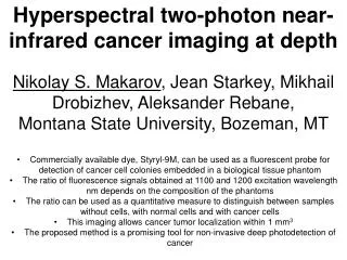
Uncooled Infrared Photon Detection Concepts and Devices. Viraj Jayaweera Piyankarage Department of Physics & Astronomy Georgia State University. Outline. Introduction Infrared Detectors based on Dye-Sensitization of Nanostructured Semiconductors

E N D
Uncooled Infrared Photon Detection Concepts and Devices Viraj Jayaweera Piyankarage Department of Physics & Astronomy Georgia State University
Outline • Introduction • Infrared Detectors based on • Dye-Sensitization of Nanostructured Semiconductors • Dye-sensitized NIR detector design, experimental results, and conclusion • 1/f Noise on DS nano structures • Displacement Currents in Semiconductor Quantum Dots (QDs) Embedded Dielectric Media • Size quantization effects • QD capacitor based detector design, experimental results, and conclusion • Split-off Band Transitions in GaAs/AlGaAs Heterojunctions • High operating temperature split-off response observed from HEIWIP design for 17μm threshold wavelength • Uncooled split-off band detector design Experimental results, and conclusion • Free Carrier Absorption in GaSb Homojunctions • GaSb HIWIP detector design, experimental results, and conclusion • Future Work
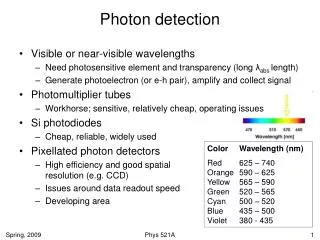
Electromagnetic Spectrum http://www.nasa.gov/centers/langley/science Near-IR Mid-IR Far-IR Micro Wave Visible 0.8 – 5 m 5 - 30 m 30 - 300 m Wavelength
1-3 μm Short Wavelength Infrared SWIR 3-5 μm Medium Wavelength Infrared MWIR 5-14 μm Long Wavelength Infrared LWIR 14-30 μm Very Long Wavelength Infrared VLWIR 30-100 μm Far Infrared FIR 100-1000 μm Sub-millimeter SubMM IR Wavelength Range Classification
Infrared Applications http://www.netcast.com.hk/Products.htm Infrared Body Temperature Thermometer Remote controller and receiver Visible Light
Human suspect climbing over a fence at 2:49 AM in total darkness Infrared image of Orion Applications Blood Flow brain imaging www.medphys.ucl.ac.uk/research/borl/ Transverse, coronal, and sagittal views across the 3D absorption image of the infant, acquired at 780 nm. Night vision helmet
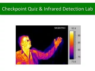
ºF Applications Thermal analysis of a fluid tank level detection Close up image of a Intel Celeron chip www.x20.org Faulty connection at power station www.x20.org Bad Insulation spots
Photo- conductive Photovoltaic Bolometric Thermoelectric Photoemissive Pyroelectric Different Types of Infrared Detectors IR Detectors Photon Thermal
Direct and Sensitized Photo-Injection LUMO CB CB HOMO VB VB Semiconductor Dye Light induced charge carrier generation in a semiconductor Dye-sensitized electron injection to a semiconductor LUMO = Lowest Unoccupied Molecular Orbital HOMO = Highest Occupied Molecular Orbital
Dye-Sensitized Near-Infrared Detectors (DSNID) n-TiO2 nanoparticles p-CuSCN IR dye TiO2 CuSCN Dye Dye p-type n-type V Solid State Device (No Liquid Electrolyte)
Structure of a dye-sensitized IR Detector CTO Transparent Conducting Tin Oxide (CTO) TiO2nanoparticles Glass n-TiO2 Dye Glass Platinum or Gold layer p-CuSCN Appl. Phys. Lett., Vol. 85, No. 23, (2004)
Energy Level Diagram: n/D/p - Heterojunction Vacuum Energy (eV) CB -1 -2 -3 -4 -5 -6 -7 -8 S* CB VB S0 VB p-CuSCN Dye n-TiO2 Appl. Phys. Lett., Vol. 85, No. 23, (2004)
IR Absorbing Dyes The number indicates the peak absorption wavelength in nanometers
Spectral Responsivity Peak Detectivity = (9.0 ± 0.3) ×1010 cm Hz½ W-1 Conversion Efficiency = 0.4 % Appl. Phys. Lett., Vol. 85, No. 23, (2004)
Colloidal QDs are synthesized from precursor compounds dissolved in solutions. Size Quantization Effects CdSe/ZnS Colloidal Quantum Dots (QDs) Emission Spectra http://www.nanopicoftheday.org/2003Pics/QDRainbow.htm ~4 nm ~15 nm
Size Quantization Effects (H. Q. Wang et al. Journal of Colloid and Interface Science, 316 (2007) 622-627) TEM images of different size quantum dots (CdSe/ZnS) with emission wavelength at: (A) 525; (B) 540; (C) 590; (D) 652; and (E) 691 nm. Average diameter: (A) 4.2 nm; (B) 4.6 nm; (C) 6.7 nm; (D) 10.6 nm; (E) 20.1 nm. Scale bar: 20 nm.
Wavelength (nm) PbS Colloidal QDs Bandgap vs. Particle size Y. Wang et al. J. Chem. Phys. 87 (1987) A. Margaret et al. Adv. Mater. 15 (2003) Bulk PbS direct band gap = 0.41 eV (λt = 3 μm) 4 nm PbS QD = 1.2 eV (λt = 1 μm)
Optical Chopper Incoming IR radiation QD Embedded Capacitor (QDEC) TypeIR Photodetectors Dielectric Micro Ammeter Battery Quantum Dot Appl. Phys. Lett., 91, 063114 2007
Schematics of the QDEC Type Infrared Photodetector Glass Top Electrical Contact Glass PbS QD + Dielectric medium Bottom Electrical Contact Transparent Conducting layer (Fluorine-doped tin oxide) • Possible dielectric materials: • Paraffin Wax • Silicon Nitride • Silicon Oxide Glass can be replaced with IR transmitting substrate such as Si, ZnSe, Sapphire, CaF2, MgF2, KRS Appl. Phys. Lett., 91, 063114 2007
Spectral Responsivity of the QDEC IR Detector PbS ~2 nm Appl. Phys. Lett., 91, 063114 2007
HEIWIP Free Carrier Detectors (Heterounction Interfacial Workfunction Internal Photoemission)
p+-GaAs AlxGa1-xAs Δ Δ VB Biased HEIWIP Detectors (Heterounction Interfacial Workfunction Internal Photoemission Detectors) p+-GaAs AlxGa1-xAs VB EF hν h Emitter Barrier Zero Bias Barrier formed by Heterojunction (p-type) Internal workfunction Δ comes from Al fraction (x) and doping Absorption is due to free carriers Interface is sharp (no space charge) APL 78, 2241 (2001) APL 82, 139 (2003)
λt Free Carrier Threshold of HEIWIP Detector p+-GaAs AlxGa1-xAs VB EF Δd Responsivity (a.u.) Δx VB Emitter Barrier Wavelength (μm) Al fraction x = 0.090 λt = Threshold Wavelength Practical Limit of x = 0.005 Practical Limit of x = 0.005 (t ~ 110 μm) NA = 3×1018 cm-3Doped p+ GaAs Emitters x = 0.000 (Homojunction) Δ= Δd + Δx
E Intersubband levels Conduction Band E E E Conduction Band Conduction Band Impurity Band k k k k Heavy Hole Band Light Hole Band EF HH Band Heavy Hole Band Heavy Hole Band Light Hole Band Light Hole Band LH Band Split-off Band Split-off Band Split-off Band SO Band INTRINSIC (InSb, HgCdTe) Extrinsic (Si:P) Split-Off QWIP (GaAs/AlGaAs) Infrared Detector Mechanisms
Split-off Detector Threshold Mechanisms E CB k p+-GaAs AlGaAs L /H Ef HH Band EBL/H LH Band EESO SO EBSO SO Band SPLIT-OFF Intra-valence Transitions Indirect absorption followed by scattering and escape Threshold Energy EESO - Ef Direct absorption followed by scattering and escape Threshold Energy EESOf - Ef Indirect absorption followed by escape without scattering Threshold Energy EBSO - Ef IR Photon excites holes from the light/heavy hole bands to the split-off band (Solid Arrow) Excited holes can scatter into the light/heavy hole bands (Dashed Arrow) and then escape, or escape directly from the split-off band IR Photon excites holes from the light/heavy hole bands to the split-off band (Solid Arrow) Excited holes can scatter into the light/heavy hole bands (Dashed Arrow) and then escape Appl. Phys. Lett., 89 131118 (2006)
Schematics of the Detector 400 μm RBias Au contact layers 400 μm Top Contact p++ GaAs N Periods <2.5μm p+ GaAs (emitter) AlGaAs (barrier) Bottom Contact p++ GaAs Substrate GaAs
Absorption and Conversion Efficiency (Initial Sample 1332, λt = 17 μm) Split-off Split-off Free Carrier αλ2 Free Carrier
207 meV 365 meV 310 meV 365 meV 365 meV SP2 SP3 Different Free Carrier Threshold (λt) Samples L /H Band 155 meV SO Band SP1 Appl. Phys. Lett., 93 021105 (2008)
Results of Different λt Samples Operating threshold dark current ~1 A/cm2 Design flexibility for higher D* or higher operating temperature
ESO – Ef = 370 meV 3.4 μm ESOf – Ef = 420 meV 2.9 μm Room Temperature Response ( SP3: 4 μm Free Carrier Threshold ) CB SP3 k Ef L/H HH Band LH Band SO SO Band SPLIT-OFF Intra-valence Transitions Appl. Phys. Lett., 93 021105 (2008)
Noise level 3 V 2 V 1 V Above Room Temperature Operation 4 V
Different Material will Cover Different Split-off Ranges Possibility of a room temperature dual band detector for atmospheric windows 3-5 and 8-14 m using Arsenides & Phosphides
Summary • High Operating Temperature (Uncooled or TE Cooled) • Tunability (Wavelength, Detectivity, Operating Temperature) • Well Developed Materials, Readout Circuits, and Integrated Circuits • High Performance
p+-GaSb Undoped GaSb Δ Δ VB Biased HIWIP(Homojunction Interfacial Workfunction Internal Photoemission Detectors) p+-GaSb Undoped GaSb VB EF hν h Emitter Barrier Zero Bias Barrier formed by Homo-junction (p-type) Δ comes from doping Absorption is due to free carriers A.G.U. Perera et al., JAP (77) 915 (1995)
GaSb HIWIP Far-IR (THz) Detector Bottom Contact Metal contact p+ GaSb 5×1018cm-3 p++ Top Contact 0.1 μm GaSb p+ GaSb 2×1018cm-3 p+ emitter 0.05 μm Undoped-GaSb barrier 2 μm ΔEV Δ 2×1018cm-3 p+ emitter 0.05 μm 5×1018cm-3 p++ GaSb Substrate Appl. Phys. Lett. 90, 111109 (2007) Grown by OMCVD
GaSb HIWIP Far-IR (THz) Response Peak Detectivity at 36 μm = (5.7 ± 0.1)×1011 cm Hz½ W-1 Conversion Efficiency = 33 % Appl. Phys. Lett. 90, 111109 (2007)
GaSb THz Absorption Why GaSb ? GaSb GaAs
InGaSb/GaSb Heterojunctions InGaSb/GaSb has a small valance band offset Much better for THz heterojunctions Barrier is ~4 meV for 1 THz Corresponds to 10% variation In fraction in Sb material < 1% Al fraction for As, N materials
Summary • Higher absorption coefficient compared to GaAs • High performance • Responsivity 9.7 A/W, Detectivity (5.7 ± 0.1)×1011 Jones at 36 μm and 4.9 K. • Wavelength tailorability • Design with 14 μm threshold expected to be work at TE cool temperatures. • InGaSb/GaSb heterojunction has a small valance band offset much better for THz designs
Colloidal Quantum Dot Based UV-NIR Dual-Band Detector PbS QDs Photo Conductive ITO ITO ZnO Glass Substrate ~10 μm In preparation to Appl. Phys. Lett.
Proposed dual band detector for 3-5 and 8-14 μm atmospheric windows using Arsenides & Phosphides p++-GaAs p+-GaAs p++-GaAs p+-In0.49Ga0.51P Al0.57Ga0.43As p++-In0.49Ga0.51P Al0.8Ga0.2As Al0.57Ga0.43As Al0.8Ga0.2As TC p++-GaAs contact 3-5 μm Response Al0.57Ga0.43As barrier p+-GaAs emitter p++-InGaP emitter Al0.57Ga0.43As barrier MC p++-GaAs contact 8-14 μm Response Al0.8Ga0.2As barrier p+-In0.49Ga0.51P emitter BC Al0.8Ga0.2As barrier p++-In0.49Ga0.51P contact GaAs substrate