Download
1 / 37
400 likes | 1.99k Views
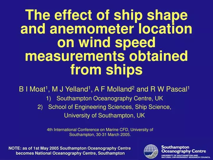
The effect of ship shape and anemometer location on wind speed measurements obtained from ships B I Moat 1 , M J Yelland 1 , A F Molland 2 and R W Pascal 1 Southampton Oceanography Centre, UK School of Engineering Sciences, Ship Science, University of Southampton, UK

E N D
The effect of ship shape and anemometer location on wind speed measurements obtained from ships B I Moat1, M J Yelland1, A F Molland2 and R W Pascal1 Southampton Oceanography Centre, UK School of Engineering Sciences, Ship Science, University of Southampton, UK 4th International Conference on Marine CFD, University of Southampton, 30-31 March 2005. NOTE: as of 1st May 2005 Southampton Oceanography Centre becomes National Oceanography Centre, Southampton
Wind speed measurements can be severely biased by the presence of the ship • CFD can be used to predict/correct wind speed measurements
OUTLINE • Background • Description of the CFD code • CFD code validation • Results • research ships (individual ships) • tankers/bulk carriers/general cargo ships (generic modelling approach) • Container ships • Conclusions
Background • Research ships limited coverage, but measurements of high quality. • Merchant ships routinely report meteorological parameters at sea surface (wind speed and direction) • Data used in satellite validation, ocean atmosphere modelling forcing and climate research
Background: impact of flow distortion on climate studies • 10 % error in mean wind speed • 27 % bias in the momentum exchange • 10 % bias in the heat exchange
CFD code description • Commercial RANS solver VECTIS • Mesh generation • Non-uniform Cartesian mesh • (generate 500,000 cells/hour) • 3-dimensional and isothermal • MEAN FLOW ONLY (STEADY STATE) • RNG turbulence model • Simulations based on up to 600,000 cells • All results normalised by the wind speed profile at the measurement site
VALIDATION • Comparison to 2 previous wind tunnel studies • Martinuzzi and Tropea (1993) • Minson et al. (1995) • Comparison to in situ wind speed measurements made from a ship • Moat et al. (2005)
Validation: channel flow over a surface mounted cube tunnel roof accelerated flow • Good comparison with RNG H = cube height Re=105 decelerated flow z/H cube top normalised wind speed
Validation: boundary layer flow over a surface mounted cube • Good comparison with RNG decelerated flow H = cube height Re=4x10⁴ z/H accelerated flow normalised wind speed
Validation: In situ wind speed measurements from RRS Charles Darwin Measurements were made using 6 anemometers. Instruments were located on a 6 m mast. Only beam-on wind speed data used. Wind speed profile measured above a ‘block like’ ship.
Validation: comparison with in situ wind speed measurements • Agreement to within 4% decelerated flow H = bridge to sea level height Re=1.3x10⁷ z/H accelerated flow normalised wind speed
Accuracy of CFD simulations • Comparisons of simulations show variations of: • Mesh density (1 %) • Turbulence model (2 %) • Scaling the geometry (3 %) • Wind speed profile (4 %) • VECTIS agrees to 4 % or better with in situ wind speed data
RESULTS: research ships • Project running since 1994 • Over 11 ships have been studied • American, British, Canadian, French and German • Present results from well exposed anemometers in the bow of 2 UK ships • RRS Discovery • RRS Charles Darwin
Results: RRS Discovery typical anemometer location • Wind speed measurements are biased by about 5 % length overall = 90 m
Results: RRS Charles Darwin typical anemometer location • Wind speed measurements are biased by about 10% length overall = 70 m
Results: research ships RRS Discovery bow Wind speed bias (%) port starboard RRS Charles Darwin Streamlined superstructure needed Locate anemometers as high as possible above the platform, not in front Relative wind direction
Research ship design: RRS James Cook Anemometer location • CFD will be used to determine the best sensor locations First steel cut 26th January 2005
RESULTS: tankers, bulk carriers and general cargo ships Typical anemometer location www.shipphotos.co.uk Large number of ships. Cannot be studied individually. The ships are large complex shapes
Results: A generic ship model • Ship dimensions from RINA publication Significant ships (1990-93) • Tankers/bulk carriers/general cargo ships can be represented by a simple shape. bow stern
Results: A generic ship model bridge anemometers • Perform CFD simulations over the simple geometry • Bridge anemometers • Flows directly over the bow bow stern
Wind tunnel: flow visulisation mean flow direction Standing vortex in front of the deck house
Wind tunnel: flow visulisation mean flow direction • Decelerated region increases with distance from the leading edge Vortices produced above the bridge top Standing vortex in front of the deck house
Wind tunnel: flow visulisation mean flow direction Less disturbance with increase in height • Complex flow pattern Vortices produced above the bridge top Standing vortex in front of the deck house
CFD: Airflow above the bridge accelerated flow 3D simulation of the airflow over the tanker. (RNG turbulence closure) decelerated flow with recirculation. Tanker Flow direction Qualitatively, the numerical model reproduces the general flow pattern quite well.
CFD: Airflow above the bridge accelerated flow. 3D simulation of the airflow over the tanker. (RNG turbulence closure) decelerated flow with recirculation. Tanker Flow direction Qualitatively, the numerical model reproduces the general flow pattern quite well.
Normalised wind speed profile • Wind speed accelerated by about 10 % • Decelerated by up to 100 % deceleration and recirculation z/H H bow stern Normalised wind speed
Normalised wind speed profile deceleration and recirculation z/H H bow stern Normalised wind speed Region of high velocity gradients
RESULTS: typical merchant ships • Anemometers will be less distorted in the bow • Locate anemometers as high above the deck as possible and above the leading edge Anemometer position Bridge height, z (m) Depth of the recirculation region Bow Distance from leading edge, x (m)
Container ships Anemometer locations • More complex shape than a typical tanker • Irregular container loading ??? www.shipphotos.co.uk
Container ships: General flow pattern 1.0 accelerated 1.0 accelerated container ship decelerated 1.0 bow bridge accelerated 1.0 1.0 accelerated decelerated decelerated (Moat et al. 2005)
Container ships: General flow pattern 1.0 accelerated 1.0 accelerated • Bow influences the bridge flow • Complex flow and the subject of future work container ship decelerated 1.0 bow bridge accelerated 1.0 1.0 typical tanker accelerated decelerated decelerated (Moat et al. 2005)
APPLICATION OF RESULTS: MERCHANT SHIPS • To predict the wind speed bias • Ship type • Ship length • Anemometer position • Parameters are now available (WMO-47)
CONCLUSIONS: Research ships • CFD is a valid research tool to examine the mean airflow over ships • anemometers biased by about 10% or less (highly dependent on position) • Streamlined superstructure needed for accurate wind speed measurements
CONCLUSIONS: Tankers/bulk carriers/general cargo • anemometers biased high by 10% and low by 100% • Position anemometers as high as possible above the deck • If possible: locate anemometers in the bows of the ship
FUTURE WORK • How does the turbulence structure change with ship shape ? time = 3 sec
FUTURE WORK • Good representation of atmospheric turbulence in the wake region of a ship LES code GERRIS Iso-surface of wind speed at 90% of the inflow velocity time = 3 sec
Acknowledgements Partial funding from Meteorological Service of Canada and the Woods Hole Oceanographic Institution, USA. Contact ben.moat@soc.soton.ac.uk www.soc.soton.ac.uk/JRD/MET/cfd_shipflow.php