Download
1 / 38
380 likes | 539 Views
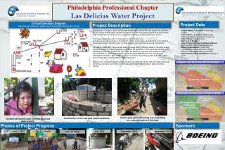
Las Delicias , El Salvador Water Supply Project. Current Project Status, January 2010 Richard Cairncross & David Haussler. Presentation Outline. Overview of Las Delicias Community Current Water Supply System and Challenges Proposed Improvement to Water System Phase I (May 2012)

E N D
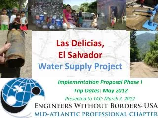
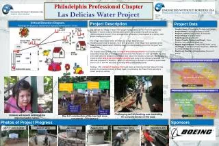
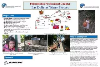
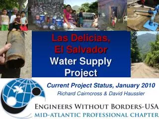
Las Delicias, El SalvadorWater Supply Project Current Project Status, January 2010 Richard Cairncross & David Haussler
Presentation Outline • Overview of Las Delicias Community • Current Water Supply System and Challenges • Proposed Improvement to Water System • Phase I (May 2012) • New Water Tank at Intermediate Elevation • New Supply pipeline and distribution pipeline • Phase II (Fall 2012) • New pump • Improvements to distribution system • Logistics and Implementation
Las Delicias, El Salvador Las Delicias
Las Delicias, El Salvador • Project History • Project FIAT and FIMRC have been active in Las Delicias for > 5 years • Initial Contact with Project FIAT • January 2009 • Application to EWB-USA • March2009 • Project Approved • May 2009 • Preliminary Assessment Visit • July 2009 • First Assessment Trip • July 2010 • Second Assessment Trip • November 2011 • Community Facts • ~600 homes, 3000 residents • 15 miles NW of San Salvador • On Western Slopes of Volcan San Salvador • Homes Spread Out, but Las Delicias is Bordered by Several Similar Communities • Water Storage & Piping System installed 20 years ago With Water Delivery by Truck • Well and Pump Installed < 5 years ago • Residents are Poor (<$10/week income) • Community Well-Organized through Adesco and NGOs (FIAT & FIMRC) • Able to spend about $5 per household on water each month
Current Las Delicias Water System DOWNHILL
Las Delicias Community Map with Piping System • Pump Runs 6 Hours a day 3 days/week. • Pump flows about 150 GPM.
Map of Las Delicias WaterSystem DOWNHILL
Map of current Las Delicias Water System from ADESCO with approx house locations indicated DOWNHILL
Current Water Distribution System 260 Homes Served by Tanque 3 291 Homes Served by Tanque 1 33 Homes Served by Tanque 2 DOWNHILL
Proposed Updates to Las Delicias Water System • Objectives • Utilize existing and new tank at intermediate elevation to supply water to lower half of Las Delicias • With new pump and supply line reduced electricity costs • Improved distribution system more equitable water supply to all homes • Phase I (May 2012) • New Water Tank at Intermediate Elevation • New Supply pipeline and distribution pipeline • Phase II (Fall 2012) • New pump • Improvements to distribution system • Improving power factor for pump • Enabling pumping during nighttime to take advantage of lower rates
Proposed Water Distribution System 280 Homes Served by New Tank 117 Homes Served by Tanque 3 33 Homes Served by Tanque 2 154 Homes Served by Tanque 1 DOWNHILL
Summary of potential changes in water distribution system CURRENT SYSTEM PROPOSED MODIFICATION Storage Tanque 1: 35,000 gal Tanque 2: 11,000 gal Tanque 3: 25,000 gal New Tank: 28,600 gal Current 65 HP Pump supplies water to Tanques 1 & 3 at 175 gpm New pump supplies water to new tank at 175 gpm with much lower head Homes serviced by Tanques 154 33 117 New: 280 • Storage • Tanque 1: 35,000 gal • Tanque 2: 11,000 gal • Tanque 3: 25,000 gal • Pump supplies water to Tanques 1 & 3 at 175 gpm, ~3 days per week • Spring supplies water to Tanque 2 (and other tanques) • Homes serviced by Tanques • 291 • 33 • 260 New tank reduces demand of water from Tanques 1&2 (which require high head) by roughly 50%
Tank Design • Concrete block vs concrete • Assumed strength of concrete • Tank seal at base of wall
Coupling system between 2 Tanks with different height/elevation
Design of Additional Pipelines for- supplying water to tank- distributing water
Map of Current Water System (section relevant for EWB-MAP modifications)RED lines – supply lines to tank (uphill by pump)BLUE lines – distributions lines by gravity DOWNHILL
Proposed update to Water System (section relevant for EWB-MAP modifications)RED lines – supply lines to tank (uphill by pump)BLUE lines – distributions lines by gravity A F NEW DISTRIBUTION LINE 2a NEW SUPPLY LINE 1 D NEW DISTRIBUTION LINE 2b E DOWNHILL NEW DISTRIBUTION LINE 2c B NEW TANK C
Piping System Layout New Pipelines Waypoints • Supply Line 1 to new tank (A-B-C) • Length = 365 m + tank connection (assume + 10 m) = 375 m • 1 bend, 1 tee, 3 elbow, 2 valves, 1 exit • 17 m elevation rise + tank height • Hill rises to 643 m then valley falls t0 640 m on connecting road (D-B) • ~175 gpmflowrate • Distribution line connection 2a from lower Tramo 3b to lower Tramo 6 (E-F) • 105 m length, elevation change unclear, guess 10 m drop • Distribution connection 2b from upper Tramo 3b to upper Tramo 6 (B-D) • 120 m length, 8 meter drop with low point at 640 m (3 m below D) • Distribution line 2c from new tank to new connections (C-B-E) • 255 m length, 11 meter elevation drop
Proposed update to Water System (section relevant for EWB-MAP modifications)RED lines – supply lines to tank (uphill by pump)BLUE lines – distributions lines by gravity A 20 m DOWNHILL 240 m NEW SUPPLY LINE 1 B NEW TANK C 105 m
NEW TANK Supply Pipe 1 Pipe Profile RoadCrossing RoadCrossing C 655 m B 651 m 105 m Elevation: 640 m D 643 m 640 m 240 m A 638 m Tee connect to 6” pipe Gate Valve 45° Elbow 90° Elbow with anchor 90° Elbow Pipe Exit Tee with Manual Air release valve Tee with Manual drain valve Gate Valve 90° Elbow PIPE FITTINGS
Estimate of head losses in supply pipe 1 (smooth PVC) 4” PVC sufficient to keep major and minor losses to <10% of the elevation change
Supply Pipe 1 Trenching • Based on recommendations from EWB Water Resource Guidelines and advice from Tony Sauder: • 70 cm trench depth (45 cm depth acceptable except in road crossing) with pipe buried below 50 cm • 10 cm bedding (2-12 mm soil) if stones/rocks present in trench • Back-fill with soil that is free of lumps, from stones (>3 cm), and from organic matter • PVC pipe joined in trench and cure for >10 hr prior to pressurizing. Keep joints exposed to check for leaks • For road crossing, may bury PVC pipe inside steel or concrete pipe (ID > diameter of PVC joints); final decision to be made in the field after evaluating potential for erosion 50 cm 70 cm trench depth 10 cm 10 cm bedding
Valve Boxes • Design options • Obtain pre-cast valve boxes with lockable lids locally • Build from bricks and mortar with metal lids • Specifications • 4” Pipe centered about 55 cm below ground level • Box should extend 10 cm above ground level • Internal dimensions roughly 45cmx45cm • Place support under valve Photos of current valve boxes installed in Las Delicias
Design of Valve Boxesfrom a prior EWB project • Adjust Dimensions based on local conditions • For Single 4” pipe
Thrust Anchors for Elbows &Tees From Russ Turner, Tetratech
Thrust Anchor Dimensions • Based on • 4” PVC PIPE • 50 cm Trench Depth • Height of Anchor • 25 cm • Length of Anchor Backing against undisturbed material: • 90° BEND: L = 80 cm • 45° BEND: L = 40 cm • Tee: L = 40 cm
Material Procurement • Emphasize connections through Project FIAT