Download
1 / 28
280 likes | 293 Views
Investigating transverse post-tensioning to enhance durability of concrete bridge decks in Indiana. Comparative analysis of SAP2000 and ANSYS modeling, evaluating variables like girder spacing, diaphragms, and boundary conditions. Preliminary identification and analysis of relevant factors impacting transverse stresses and T-beam analogy for diaphragm position influence.

E N D
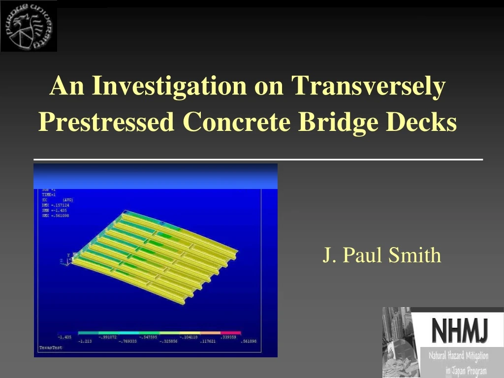
An Investigation on Transversely Prestressed Concrete Bridge Decks J. Paul Smith
Objective Study of transverse post-tensioning of concrete bridge decks as an alternative to improve durability.
Scope Develop design specifications applicable to: • Slab bridges • Slab-on-Girder bridges
Problem Statement q [F/L] s? Assumption: Linear behavior
Specimen for Experimental Phase of Texas Study Location of strain gages 1.2ksi 0.6ksi 1.2ksi
Modeling Alternatives (SAP2000) beam • 2D Model shell Girders and diaphragms as beams (Type I) • 3D Model • (slab as shell) Diaphs. as shells (Type II) Flanges as beams and webs as shells Diaphs. as beam (Type III)
Comparison of Analytical (SAP2000) & Experimental (Texas Study) Results Top Stresses Modeling Type 2D 3D(I) 3D(II) 3D(III) m 16 14 14 14 Max 40 38 38 42 m = mean[(ss/sexp)-1]x100% Max = Max[(ss/sexp)-1]x100%
Analysis using ANSYS 5.7 • Alternative modeling: • Use brick and shell elements
Variables of Interest • Girders (spacing, stiffness) • Diaphragms (spacing, stiffness, location) • Boundary conditions • Post-tensioning spacing • Slab thickness
q/h = 100 q/h = 100 Base Case 22 in.
Preliminary Evaluation of Variables (2D Modeling) • Base Case:
Preliminary Evaluation of Variables (2D Modeling) • Effect of Girder Spacing: a) Half Spacing b) Quarter Spacing
Preliminary Evaluation of Variables (2D Modeling) • Effect of Girder (No diaphragms): a) Concrete girders b) Steel girders
Preliminary Evaluation of Variables (2D Modeling) • Effect of Diaphragms: Top half: diaphragms present Bottom half: diaphragms no present
Fully restrained except against displacement in x Restrained against displacement in x Preliminary Evaluation of Variables (2D Modeling) • Effect of boundary conditions:
Preliminary Evaluation of Variables (2D Modeling) • Effect of Post-tensioning Spacing: a) Forces at every other node: b) Forces every four nodes: @ 4’ @ 8’
Preliminary Evaluation of Variables (2D Modeling) • Effect of Slab Thickness: 8” slab 6” slab
Preliminary Identification of Relevant Variables (2D Modeling) • Diaphragms (stiffness, location, spacing) • Boundary conditions • Post-tensioning spacing
Effect of Diaphragms Distribution of transverse stresses is mainly affected by diaphragm size and location.
Notation Normalized stress = ss/q y x
Effect of Diaphragm Size y y Stripe 1 Stripe 2
Effect of Diaphragm Location(Exterior Diaphragms Only) y y Stripe 2 Stripe 1
1.00 0.90 0.80 0.70 Beff x h 0.60 0.50 0.40 100 300 400 50 150 250 350 0 200 Beff (in.) Diaphragm Location vs. Effective Width
Conclusions at this Stage • Distribution of transverse stresses mainly influenced by: • Diaphragm axial stiffness and position • Boundary conditions • Influence of diaphragm position: Rationalized using T-beam analogy