Download
1 / 30
300 likes | 324 Views
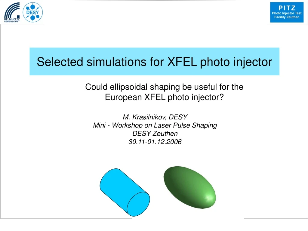
Explore the potential benefits of ellipsoidal shaping for the European XFEL photo injector through selected simulations. Optimization strategies, thermal emittance, and the influence of laser shape are analyzed.

E N D
Selected simulations for XFEL photo injector Could ellipsoidal shaping be useful for the European XFEL photo injector? M. Krasilnikov, DESY Mini - Workshop on Laser Pulse Shaping DESY Zeuthen 30.11-01.12.2006
Outline • Optimization of the XFEL photo injector • Specifications and layout • Optimization strategy • Flat-top laser (cylindrical laser pulse shape) • Influence of the thermal emittance • Ellipsoidal cathode laser shape • Flat-top imperfection influence • Conclusions M.Krasilnikov, DESY
XFEL Photo Injector Specifications • 1 nC charge • Uniform transverse distribution • Longitudinal flat-top 20 ps with 2 ps rise time • Emittance 0.9 mm mrad incl. thermal emittance • 60 MV/m at photo cathode M.Krasilnikov, DESY
XFEL photo injector layout Superconducting TESLA module (ACC1) RF gun M.Krasilnikov, DESY
Optimization of the XFEL photo injector Cathode laser (XYrms, [Trms]) + gun parameters (RF Phase, Imain, [sol.pos]) [ ] Booster optimization (booster cavity z-position, gradient and RF phase) Initial guess: booster matching conditions Emittance (+slope) 0 step. “tune” the bunch charge: Qbunch->Q=1nC(@z=5cm) Emission effects (SC, Schottky) Xrms,Xemit 1 step. Run ASTRA till z=5m M.Krasilnikov, DESY
Thermal emittance Thermal emittance measured at PITZ is higher than expected from theoretical predictions (Schottky effect, cath. roughness) Ek=0.55 eV ph=4.75 eV M.Krasilnikov, DESY
Simulation Cases 2 3 1 6 4 7 5 Thermal emittance Ek=0.55 eV Ek=1.0 eV Cylindrical laser shape emittance Elliptical laser shape M.Krasilnikov, DESY
Optimization of the XFEL photo injector Case 1: Cylindrical laser shape, flat-top intensity profile 20 ps FWHM 2 ps rise/fall time • Optimized parameters: • Cathode laser XYrms • RF gun launch phase • Main solenoid peak field* • Booster z-position • Booster gradient • Booster RF phase • *Bucking solenoid - always compensated M.Krasilnikov, DESY
Optimization of the XFEL photo injector Bunch slice parameters @ z=15m Case 1: Cylindrical laser shape, flat-top intensity profile M.Krasilnikov, DESY
Optimization of the XFEL photo injector Bunch slice emittance @z=15m Case 2: Cylindrical laser shape, flat-top intensity profile. Increased thermal kinetic energy 0.55 eV → 1.0eV M.Krasilnikov, DESY
XFEL photo injector: Influence of the thermal emittance • ?Further optimization: • Cathode laser XYrms • RF gun launch phase • Main solenoid peak field • Booster z-position • Booster gradient • Booster RF phase M.Krasilnikov, DESY
Optimization of the XFEL photo injector Bunch slice emittance @z=15m Case 3: Cylindrical laser shape, flat-top intensity profile. Increased thermal kinetic energy 1.0eV, optimized Only tiny emittance improvement! M.Krasilnikov, DESY
Laser Shape: Ellipsoid instead of Cylindrical Trms=5.8 ps XYrms=0.44 mm 20 ps FWHM 2 ps rise/fall time M.Krasilnikov, DESY
XFEL photo injector: Ellipsoid Vs. Cylinder Bunch slice emittance @z=15m Case 4: 3D-ellipsoidal laser shape. Ek=0.55eV M.Krasilnikov, DESY
XFEL photo injector: Ellipsoid Vs. Cylinder Case 5: 3D-ellipsoidal laser shape. Ek=0.55eV, optimized • Optimized parameters: • Cathode laser XYrms • Cathode laser Trms • RF gun launch phase • Main solenoid peak field* • Booster gradient • Booster RF phase • *Bucking solenoid - always compensated M.Krasilnikov, DESY
XFEL photo injector: Ellipsoid Vs. Cylinder Charge density and slice emittance M.Krasilnikov, DESY
XFEL photo injector: Ellipsoid with Ek=1.0 eV Case 6: 3D-ellipsoidal laser shape. (=case 5 + Ek=1.0eV) M.Krasilnikov, DESY
XFEL photo injector: Ellipsoid Vs. Cylinder Case 6: 3D-ellipsoidal laser shape. (=case 5 + Ek=1.0eV) M.Krasilnikov, DESY
XFEL photo injector: Ellipsoid with Ek=1.0 eV Case 7: 3D-ellipsoidal laser shape, Ek=1.0eV . optimized M.Krasilnikov, DESY
XFEL photo injector: Ellipsoid Vs. Cylinder Case 7: 3D-ellipsoidal laser shape, Ek=1.0eV . optimized M.Krasilnikov, DESY
XFEL photo injector: Ellipsoid Vs. Cylinder Charge density and slice emittance. Ek=1.0eV M.Krasilnikov, DESY
Ellipsoid Vs. Cylinder: Emittance Summary Projected Slice (centre) M.Krasilnikov, DESY
XFEL photo injector: Ellipsoid Vs. Cylinder Electron bunch (z,x) @z=15m, cylindrical cathode laser shape Electron bunch (z,x) @z=15m, ellipsoidal cathode laser shape M.Krasilnikov, DESY
Laser shape fine adjustment cathode laser shape electron bunch @z=1cm M.Krasilnikov, DESY
Cathode laser imperfections cath.laser profile cath.laser profile Emittance growth due to flat-top modulation M.Krasilnikov, DESY
Cathode laser imperfections: FT modulation Cathode laser intensity and electron bunch density M.Krasilnikov, DESY
Cathode laser imperfections: FT modulation Microbunching instability gain (courtesy M.Dohlus) Electron bunch density modulation vs. cathode laser intensity modulation 30 n=5l=1.1mm n=3l=1.7mm n=1l=4mm M.Krasilnikov, DESY
By optimization the main parameters of the XFEL photo injector one can simulate rather small projected normalized emittance: Slice emittance of the bunch centre reduced in ~10% by applying an ellipsoid laser pulse. Main reduction of the projected emittance is due to significant decrease in head and tail slice emittance of the ellipsoid But practical realization can face problems of shape imperfections (tight tolerances) Conclusions M.Krasilnikov, DESY
Optimization of the XFEL photo injector • Based on ASTRA simulations • Actual solenoid position • Strategy: 2-staged* optimization • 1. Only gun (Ecath=60MV/m) • 2. Booster (first ½ of ACC1) Scan of the second ½ of ACC1 gradient • Goal function: emittance (incl. slope) • Penalty function: charge, momentum spread, variable parameters range M.Krasilnikov, DESY