Download
1 / 22
230 likes | 370 Views
PIPELINING 2 nd week. PIPELINING 2 nd week. References Pipelining concepts The DLX architecture A simple DLX pipeline Pipeline Hazards and Solution to overcome. REFERENCES . Computer Architecture: A Quantitative Approach, John L Hennessy & David a Patterson , Chapter 6.

E N D
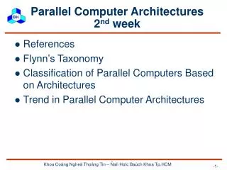
PIPELINING 2nd week • References • Pipelining concepts • The DLX architecture • A simple DLX pipeline • Pipeline Hazards and Solution to overcome Khoa Coâng Ngheä Thoâng Tin – Ñaïi Hoïc Baùch Khoa Tp.HCM
REFERENCES • Computer Architecture: A Quantitative Approach, John L Hennessy & David a Patterson, Chapter 6 Khoa Coâng Ngheä Thoâng Tin – Ñaïi Hoïc Baùch Khoa Tp.HCM
PIPELINE CONCEPTS • A technique to make fast CPUs by overlapping execution of multiple instructions Cycles Instruction # 1 2 3 4 5 6 7 8 Instruction i IF ID EX WB Instruction i+1 IF ID EX WB Instruction i+2 IF ID EX WB Instruction i+3 IF ID EX WB Instruction i+4 IF ID EX WB Khoa Coâng Ngheä Thoâng Tin – Ñaïi Hoïc Baùch Khoa Tp.HCM
PIPELINE CONCEPTS (cont’d) • Pipeline throughput • Determined by how often an instruction exists the pipeline • Depends on the overhead of clock skew and setup • Depends on the time required for the slowest pipe stage • Pipeline stall • Delay the execution of some instructions and all succeeding instructions • “Slow down” the pipeline • Pipeline Designer’s goal • Balance the length of pipeline stages • Reduce / Avoid pipeline stalls Khoa Coâng Ngheä Thoâng Tin – Ñaïi Hoïc Baùch Khoa Tp.HCM
PIPELINE CONCEPTS (cont’d) Average instruction time without pipeline Pipeline speedup = Average instruction time with pipeline CPI without pipelining * Clock cycle without pipelining = CPI with pipelining * Clock cycle with pipelining ( CPI = number of Cycles Per Instruction) = CPI without pipelining Ideal CPI * Pipeline depth = CPI with pipelining Ideal CPI + Pipeline stall clock cycles per instruction Thus Ideal CPI * Pipeline depth Pipeline speedup = Ideal CPI + Pipeline stall clock cycles per instruction Khoa Coâng Ngheä Thoâng Tin – Ñaïi Hoïc Baùch Khoa Tp.HCM
THE DLX ARCHITECTURE • A mythical computer which architecture is based on most frequequently used primitives in programs • Used to demonstrate and study computer architecture organizations and techniques • A DLX instruction consists of 5 execution stages • IF – instruction fetch • ID – instruction decode and register fetch • EX- execution and effective address calculation • MEM – memory access • WB- write back Khoa Coâng Ngheä Thoâng Tin – Ñaïi Hoïc Baùch Khoa Tp.HCM
Cycles Instruction # 1 2 3 4 5 6 7 8 Instruction i IF ID EX MEM WB WB Instruction i+1 IF ID EX MEM WB Instruction i+2 IF ID EX MEM WB Instruction i+3 IF ID EX MEM A SIMPLE DLX PIPELINE • Fetch a new instruction on each clock cycle • An instruction step = a pipe stage Khoa Coâng Ngheä Thoâng Tin – Ñaïi Hoïc Baùch Khoa Tp.HCM
PIPELINE HAZARDS • Are situations that prevent the next instruction in the instruction stream from executing during its designated cycles • Leads to pipeline stalls • Reduce pipeline performance • Are classified into 3 types • Structural hazards • Data hazards • Control hazards Khoa Coâng Ngheä Thoâng Tin – Ñaïi Hoïc Baùch Khoa Tp.HCM
STRUCTURAL HAZARD • Due to resource conflicts • Instances of structural hazards • Some functional unit is not fully pipelined • a sequence of instructions that all use that unit can not be sequentially initiated • Some resource has not been duplicated enough. Eg: • Has only 1 register-file write port while needing 2 write in a cycle • Using a single memory pipeline for data and instruction • Why we allow this type of hazards? • To reduce cost. • To reduce the latency of the unit Khoa Coâng Ngheä Thoâng Tin – Ñaïi Hoïc Baùch Khoa Tp.HCM
DATA HAZARD • Occurs when the order of access to operands is changed by the pipeline, making data unavailable for next instruction • Example: consider these 2 instructions ADD R1, R2, R3 ( R2 + R3 R1) SUB R4, R1, R5 ( R1 – R5 R4) Cycles Instruction # 1 2 3 4 5 6 7 8 WB Data written here ADD instruction IF ID EX MEM SUB instruction IF ID EX MEM WB Data read here instruction is stalled 2 cycles Khoa Coâng Ngheä Thoâng Tin – Ñaïi Hoïc Baùch Khoa Tp.HCM
WB IF ID EX MEM IF ID EX MEM WB IF ID EX MEM WB IF ID EX MEM WB IF ID EX MEM WB HARDWARE SOLUTION TO DATA HAZARD • Forwarding (bypassing/short-circuiting) techniques • Reduce the delay time between 2 depended instructions • The ALU result is fed back to the ALU input latches • Forwarding hardware check and forward the necessary result to the ALU input for the 2 next instructions ADD R1, R2, R3 SUB R4, R1, R5 No stall AND R6, R1, R7 No stall OR R8,R1,R9 No stall XOR R1, R10, R11 Khoa Coâng Ngheä Thoâng Tin – Ñaïi Hoïc Baùch Khoa Tp.HCM
TYPES OF DATAHAZARDS • RAW(Read After Write) • Instruction j tries to read a source before instruction i writes it • Most common types • WAR(Write After Read) • Instruction j tries to write a destination before instruction i read it to execute • Can not happen in DLX pipeline. Why? • WAW(Write After Write) • Instruction j tries to write a operand before instruction i updates it • The writes end up in the wrong order • Is RAR (Read After Read) a hazard? Khoa Coâng Ngheä Thoâng Tin – Ñaïi Hoïc Baùch Khoa Tp.HCM
SOFTWARE SOLUTION TO DATA HAZARD • Pipeline scheduling (Instruction scheduling) • Use compiler to rearrange the generated code to eliminate hazard. Example: Generated and rearranged code (no hazard) Source code Generated code a=b+c d=e-f LW Ra, a LW Rb, b ADD Rc, Ra, Rb SW c, Rc LW Re, e LW Rf, f SUB Rd, Re, Rf SW d, Rd LW Ra, a LW Rb, b LW Re, e ADD Rc, Ra, Rb LW Rf, f SW c, Rc SUB Rd, Re, Rf SW d, Rd Data hazards Khoa Coâng Ngheä Thoâng Tin – Ñaïi Hoïc Baùch Khoa Tp.HCM
CONTROL (or BRANCH) HAZARD • Occurs when a branch/jump instruction is taken • Causes great performance loss • Example: The PC register changed here Unnecessary instruction loaded Khoa Coâng Ngheä Thoâng Tin – Ñaïi Hoïc Baùch Khoa Tp.HCM
REDUCING CONTROL HAZARD EFFECTS • Precdict whether the branch is taken or not • Compute the branch target address earlier • Use many schemes • Pipeline freezing • Predict-not-taken scheme • Predict-taken scheme (N/A in DLX) • Delayed branch Khoa Coâng Ngheä Thoâng Tin – Ñaïi Hoïc Baùch Khoa Tp.HCM
PIPELINE FREEZING • Hold any instruction after the branch until the branch destination is known • Simple but not efficient Khoa Coâng Ngheä Thoâng Tin – Ñaïi Hoïc Baùch Khoa Tp.HCM
PREDICT-NOT-TAKEN SCHEME • Predict the branch as not taken and allow execution to continue • Must not change the machine state til the branch outcome is known • If the branch is not taken: no penalty • If the branch is taken: • Restart the fetch at the branch target • Stall one cycle Khoa Coâng Ngheä Thoâng Tin – Ñaïi Hoïc Baùch Khoa Tp.HCM
PREDICT-NOT-TAKEN SCHEME (cont’d) • Example Instruction Fetch restarted Right instruction fetched Khoa Coâng Ngheä Thoâng Tin – Ñaïi Hoïc Baùch Khoa Tp.HCM
BRANCH DELAYED • Change the order of execution so that the next instruction is always valid and useful • “From before” aproach ADD R1, R2, R3 If R2=0 then If R2=0 then becomes Delay slot ADD R1, R2, R3 Khoa Coâng Ngheä Thoâng Tin – Ñaïi Hoïc Baùch Khoa Tp.HCM
BRANCH DELAYED ( cont’d) • “From target” approach SUB R4,R5,R6 ADD R1, R2, R3 If R1=0 then ADD R1, R2, R3 If R1=0 then becomes Delay slot SUB R4,R5,R6 Khoa Coâng Ngheä Thoâng Tin – Ñaïi Hoïc Baùch Khoa Tp.HCM
ADD R1, R2, R3 If R1=0 then ADD R1, R2, R3 If R1=0 then SUB R4,R5,R6 becomes SUB R4,R5,R6 Delay slot BRANCH DELAYED ( cont’d) • “From fall through” approach Khoa Coâng Ngheä Thoâng Tin – Ñaïi Hoïc Baùch Khoa Tp.HCM