Download
1 / 65
650 likes | 769 Views
Visual Communication in the AQUA environment. Technical aspects and solutions Stefan Seipel Lars W. Pettersson Björn Andersson Uppsala University. We are situated in a co-located multiple viewing environment. Co-located multiple viewing environments.

E N D
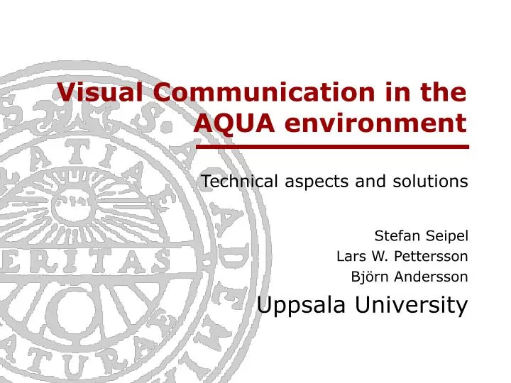
Visual Communication in the AQUA environment Technical aspects and solutions Stefan Seipel Lars W. Pettersson Björn Andersson Uppsala University
We are situated in a co-located multiple viewing environment
Co-located multiple viewing environments • Example: iRoom [Fox2000]Based on conventional 2D GUI http://graphics.stanford.edu/projects/iwork/room/images/using-room-feb-00/
Co-located multiple viewing environments • The AQUARIUM [Sundin2000]Beyond the 2D graphical user interface
Why is 3D so interesting ? Example of what could be done with 3D representations
Do existing tools fix the job? • NetVR • Full transparency and SG/DB replication • Latency issues not a predominant issue • Concurrency of media streams more important • Cluster/Tiled Rendering • Optimization • Single data multiple processes • Single data multiple displays
AQUARIUM – A 3D Interactive Environment • Specific requirements • Tiled displays • Multiple view ports • Image superimposition • Multiple views on a shared 3D scene • Individual views on private data • Co-location of multiple displays
AQUARIUM – A 3D Interactive Environment • Specific requirements • Tiled displays • Multiple view ports • Image superimposition • Multiple views on a shared 3D scene • Individual views on private data • Co-location of multiple displays
AQUARIUM – A 3D Interactive Environment • Specific requirements • Tiled displays • Multiple view ports • Image superimposition • Multiple views on a shared 3D scene • Individual views on private data • Co-location of multiple displays
AQUARIUM – A 3D Interactive Environment • Specific requirements • Tiled displays • Multiple view ports • Image superimposition • Multiple views on a shared 3D scene • Individual views on private data • Co-location of multiple displays
AQUARIUM – A 3D Interactive Environment • Specific requirements • Tiled displays • Multiple view ports • Image superimposition • Multiple views on a shared 3D scene • Individual views on private data • Co-location of multiple displays
How to design applications… …that support “20 eyes upon 15 visuals” ? • Multiple processes • Allow for flexible configuration • Management of visual views • Provide multiple interaction contexts • Easy to use programming concepts
Client 1 Client 2 srAPI srAPI srAPI srAPI Controlling by sharing data • Shared State Repository [Lindkvist2001] • Client-Server architecture • Lean and easy to use API • Based on TCP, UDP or MC • Small data subscription packages • No concurrence control srAlloc srFree srGet srUpdate ... Virtual Shared Memory TCP/UDP Client n Server
Application Application srAPI VR-Tool VR-Tool Low Level 3D (OpenGL) Low Level 3D (OpenGL) Rendering HW Rendering HW Display Display AQUARIUM application Data Pools • Pooling context relevant data projector pool srAPI pipe pool AQUARIUM application node pool
Data Pools • Pooling context relevant data projector pool how? Viewing frustum Head position Real world metrics where? pipe pool Buffer specific Pixel metrics Reference to a projector what? node pool
An Example Scenario Retroscope1 Retroscope2 Vsionarium1 Vsionarium2 View Manager Tracker 1
What about performance? • Latency and frame incoherence will introduce visual artifacts! • Little research done • Edge discontinuity • Hyper- or hypo-parallax • Vertical parallax • Peripheral viewing artifacts
Client 2 Client 1 Render Render Server 1 Capture& Analysis General test set-up: pool • 2 Rendering processes • 1 Animation process • Simple scene • Register output • Analyze differences • Observation: # frames out-of-sync.
fan server stefan: Test A : Local host Host 1 200 frames AVI Sequence Client1 800x300 fr~80Hz Differential Analysis Client2 800x300 frame grabber 800x600 fr~80Hz 20 Hz PIII/2.2GHz, GeForce4 4600 1 animated node va = 90°/sec. const. Animation rate: 10Hz, 20Hz, 30Hz, 40Hz, 50Hz
fan server stefan: Test B : Local area network Host 2 Host 1 200 frames AVI Sequence Client1 800x300 fr~80Hz LAN 10/100 MBit Differential Analysis Client2 800x300 frame grabber 800x600 fr~80Hz 20 Hz PIII/2.2GHz, GeForce4 4600 PIII/500MHz, E&S 1 animated node va = 90°/sec. const. Animation rate: 10Hz, 20Hz, 30Hz, 40Hz, 50Hz
stefan: Results for Test A and Test B #differing pixels Animation rate Local host Frame number #differing pixels Animation rate LAN Frame number
stefan: Results for Test A and Test B
stefan: Test C and D : Traffic • LAN configuration as in Test B • Increasing the number of shared states Host 2 Host 1 200 frames AVI Sequence Client1 800x300 fr~80Hz fan LAN 10/100 MBit Differential Analysis Client2 800x300 frame grabber 800x600 fr~80Hz 20 Hz server PIII/2.2GHz, GeForce4 4600 PIII/500MHz, E&S va = 90°/sec. const. Test C: (10 Hz; 1,10,20,40,60,80,100,120,140,160,180,200) Test D: (20 Hz; 1,10,20,40,60,80,100,120,140,160,180,200)
stefan: Results for Test C and Test D
Conclusion • Framework allows for building modular complex visualization environments • Flexible to use and combine with existing tools • No need for fancy protocols to maintain adequate frame-sync.
The fusion 2D and 3D Interfaces • The AQUARIUM is a 3D environment • How can legacy code be re-used? • Can 2D applications be instantiatedwithin a 3D environment?
Virtual Network Computing • System for sharing frame-buffers/applications • Developed by AT&T Laboratories Cambridge, 1999 • Open Source • Remote Frame Buffer Protocol well documented • Servers and clients readily available for Microsoft Windows, Unix, Linux och MacOs • Bold servers, thin clients
x y x x’ y’ y A 3D VNC Client • Decode RFB protocol • Administrate local texture buffers • Handle 3D input and map to 2D server coordinates
3D VNC Application • Example in the AQUARIUM Contextual browsing of auxiliary information on the WEB
3D VNC Performance Assessment • Benchmarking • Frame rate • Delay • Common Interaction • Text editing • Mouse movement • Web browsing • Streaming videos
Modular Application Development • The VASE development framework • Background • The framework & component design • Communication between components
Background • Until now – monolithic application • Different but similar applications • Many components reappear in several of the applications • Makes modular development natural • Framework that handles this is needed (VASE) • Easy script (XML) • The modular approach enables a parallel development process
Middlewares used • VRT – Virtual Reality Toolkit • For graphics handling • Built on top of OpenGL • Implements a scenegraph • STREEP • For network communication • Shared state repository • Supports both TCP and UDP
Design of the framework and the basic structure of the plugins Main module • The framework defines the basic structure for the components (plugins) • Implements a main module • Each plugin is written as a DLL and implements a class, which structure is inherited from a base class • Plugins are dynamically linked during execution • Easy to change or create new plugins when new functionality is to be added Plugin instance Plugin DLL Class implementation
Plugin pool Plugin DLLs Plugin DLLs The main module • The main module (vase.exe) handles: • Parsing of a configuration file (*.vas) • Loading and creation of plugin instances • Distributes user interaction events • Handles message passing • Handles shared states ”myfile.vas” <component type=vpiAvatar name=”client> <translate>0 -2 3</translate> <rotate>0 -90 0</rotate> <size>2</size> </component> Huvudmodul (VASE.exe) Plugin1 Plugin2 Plugin3
Example configuration file <vase> <component type="AquaViewer" name="tablet_pc_viewer"> <projector>TABLET_PC_VIEW <width>207</width> <height>138</height> <front>50</front> <back>100</back> <window_center>0.0 0.0 0.0</window_center> <window_normal>0.0 1.0 0.0</window_normal> <window_up>0 0.0 -1.0</window_up> <view_point>0.0 200.0 0.0</view_point> </projector> <pipe>TABLET_PC_PIPE <projector>TABLET_PC_VIEW</projector> <left>0</left> <bottom>0</bottom> <width>1024</width> <height>768</height> </pipe> </component> <component type="AquaWhiteboard" name="wtboard"> <translate>0 0 3</translate> <rotate>0 0 -90</rotate> <scale>1 1 1</scale> <bgcolor_r>0</bgcolor_r> <bgcolor_g>0</bgcolor_g> <bgcolor_b>0</bgcolor_b> <show_pointer>0</show_pointer> </component> </vase>
Shared state repository Main module Main module Plugin1 Plugin2 Communication Main module • Local communication • Function calls to the main module • Method calls • Network communication • Uses STREEP • Through the main module • Message passing • Receiving plugin concatinated to the message • Shared states • Subscription lists keeps track of who is interested in what Plugin1 Plugin2 Client 1 Client 2
Example of Aqua components (plugins) • AquaController • 3D-buttons • Sends messages to other plugins • AquaEchelon • Draws an echelon graph • Listens to parsed Stratmas data • Implements an internal XML structure for units • AquaEnvironment • Handles the drawing of the • map • grid • AquaParser • Inuput: Stratmas generated data file • Output: Parsed binary file • Distributes the parsed data to other plugins • AquaViewer • Handles projectors and pipes • Tracking devices • AquaWhiteboard • Overlay for the map • Stores strokes in RT90 coordinates
How do we connect the AQUA environment to the rest of the world? • The STRATMAS-Link • Modifications to STRATMAS • Socket connectivity • File connectivity • XML encoding
The STRATMAS Link- Modifications to STRATMAS • TCP socket communication add in a thread • conf.dat (link to) • ID number for each Unit
The STRATMAS Link- Socket connectivity • Connection on an hostname and port specified in conf.dat • XML data is sent in fixed sized blocks over the socket connection • Communication is one way
The STRATMAS Link- File connectivity • Generation of data.txt on the Mac running STRATMAS • Xml encoded (see next slide)
The STRATMAS Link- XML for Units int ID; long superior_ID; // -1 if no superior int rank; // 0-6 - enum RankType float latitude; float longitude; int purpose; // 0-13 - enum PurposeType int vehicle_type; // 0-6 - enum VehType, -1 if no vehicle int unit_type; // 0-8 - enum UnitType int condition; // 0-100 int health; // 0-2 - enum HealthType long my_threat; // Larger value - larger threat float sens_range; // Sensor range in km, -1 if no sensors float veh_sens_range; // Vehicle sensor range in km, -1 if no vehicle float weapon_range; // Shoot radius in km, -1 if no vehicle long shots_fired; // Number of shots fired long fi_injured; // Number of enemies injured long fi_killed; // Number of enemies killed float vx; // vehicle velocity vector in degrees *lng* per // iteration, -1 if no vehicle float vy; // vehicle velocity vector in degrees *lat* per // iteration, -1 if no vehicle float speed_kph; // vehicle speed in kilometers per hour, -1 if no vehicle float goal_x; // goal position RT90x float goal_y; // goal position RT90y int flag; // Flag for red, green or blue unit. Values: 0, 2 or 1.
The STRATMAS Link- XML for Grid int rows; // Number of rows in the grid. int cols; // Number of columns in the grid. int nc; // Number of cells holding relevant data. int nlayers; // Number of layers. char lname[MAX_GRID_LAYERS][64]; // Layer names. int *index; // Array of the cell-indices corresponding to the data array indices float *data; // The values for each layer are stored sequencially after eachother. for red, green or blue unit. Values: 0, 2 or 1.
0/1600000 700000/1600000 0/0 700000/0 28 x 64 cells á 25x25 km (1:25000) Map View 15º48’29.8’’Ö 7700000 • Topographic context • Based on RT90 coordinate reference • Mapped upon internal grid 50kmx50km Scale 1:100.000 6100000 1200000 1500000 1900000
Map View contd. 2 textures 1024x1024 texels 1024x1024 texels 1600000 [meters (RT90)] Map cell 25 x 25 km 32 x 32 texels 1 texel ~ 780 meters 700000 [meters (RT90)] Modeling unit in the virtual environment is 1cm (1:1000000) -> Map (70cmx160cm) fits visionarium
Map View summary • Map granularity can be adapdedAt present topography is schematic • High resolution map data can be loaded dynamically per map cell (e.g. 1:25000 maps per cell) depending on zoom level • Advantage of RT90 reference frame internal representation of 3D data always Euklidean orthogonal system eases texture mapping use lat/long conversion routines by metria
Cell Grid Layer • Co-located with the RT90 map • Mapps geographically related information upon map • Grid cell contain aggregated data for military units • Grid cell contain substrate information • Grid cell can visualize itself • Grid size and resolution can be chosen arbitrarily • Current limits:Max cell size: 200x200 km2=> 32 cells/RT90 map Min cell size: 3.125 x 3.125 km2=> 114688 cells/RT90 map
num_red : 0, 1,2,3,4,5 => number of red troups in 5 levels 0 = no red troups num_blue: 0, 1,2,3,4,5 => number of blue troups in 5 levels 0 = no red troups num_green: 0, 1,2,3,4,5 => number of green troups in 5 levels 0 = no green troups age: 0, 1,2 => 0 = very up-to-date information; 1 = older; 2=very old sensor: 0, 1 => 0 = there is no sensor coverage; 1 = sensor coverage disease: 0, 1,2 => 0 = no disease; 1 = disease1; 2 = disease2 strenght_red: 0, 1,2,3 => 0 = perfect strenght, 1,2,3 dicreasing moral/strenght strenght_blue: 0, 1,2,3 => 0 = perfect strenght, 1,2,3 dicreasing moral/strenght strenght_green:0, 1,2,3 => 0 = perfect strenght, 1,2,3 dicreasing moral/strenght combat: 0, 1,2 => 0 = no fight; 1 = little fight; 2 = heavy fight Cell Properties • Cell geometry (polygon) • Cell texture • Cell related data