Download
1 / 78
780 likes | 801 Views
This conceptual design review outlines the key details of a profitable supersonic aircraft for Trans-Pacific travel. The design prioritizes range, cruise speed, efficiency, and marketing aspects for airlines and passengers. The aircraft features a Fast Cranked-Arrow Wing planform, under-nose cameras for landing assist, low-boom technology, and innovative engine placement choices. With key design parameters and choices highlighted, the efficient and luxurious 40-passenger aircraft aims to revolutionize air travel.

E N D
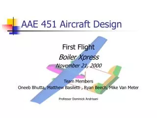
GoldJet Aerospace Conceptual Design ReviewAAE 451 Andrew Mizener Diane Barney Jon Coughlin Jared Scheid Mark Glover Michael Coffey Donald Barrett Eric Smith Kevin Lincoln
Outline G J FAST Mission and Concept Sizing Design Choices Aerodynamics Propulsion Structures Weights and Balance Stability and Control Cost Summary and Conclusions
Our Mission and Requirements • Mission Statement: • To design a profitable, supersonic aircraft capable of Trans-Pacific travel to meet the needs of airlines and their passengers around the world. • Major Design Requirements • Trans-Pacific Range • Longer range increases available routes • High Cruise Speed • Makes shorter trip times and allows for more legs per day • Good Cruise Efficiency • Lowers the cost of fuel and the max gross weight
Marketing and Sales • Passengers • High Speed Travel • Comfort • Airlines • Passengers who place high value on their time • Capstone Aircraft • Expect to sell 120 Aircraft • Projecting market growth to 2020 • Based on Key City Pairs • Long enough to provide time savings • Travelled enough to provide market foothold
Walk-Around FAST Cranked-Arrow Wing Planform Vertical Tail (No Horizontal Tail) 40 Passenger Luxury Cabin G J Under-Nose Cameras for Landing Assist 4 Low-Bypass Turbofans Under Wing Canards for Pitch Control and Low Boom
Key Design Parameters • Wing • Wing Loading: 130 lb/ft2 • Area: 2541.5 ft2 • Sweep: 60° — 57° • Span: 80.26 ft • Aspect Ratio: 1.85 • Canard • Area: 500ft2 • Sweep: 45° • Span: 40ft • Aspect Ratio: 3.2 • Sonic Boom • Overpressure: 0.36 lb/ft2 • General Performance • Range: 4800 nmi • Passengers: 40 • Length: 190 ft • Takeoff Distance: 11,400 ft • Landing Distance: 7,380 ft • Weight • W0 = 329,000 lb • We = 135,000 lb • Wf = 185,000 lb • Engine • Number: 4 • Diameter: 4.7 feet • TSL: 35,400 lbs • T/W: 0.425
Design Mission • Los Angeles (LAX) – Tokyo (NRT) • Range: 5,451 nautical miles • Reduced from LAX – PDG to save weight
Cabin Layout Length: 70 feet Aisle Width: 26 inches Aisle Height: 76 inches Seat Pitch: 40 inches
Design Choices Cranked-Arrow Planform (Herrmann, 2004) • Joined Wing • Major structural concerns • Unclear aerodynamic benefits • Too complex for time allotted • Double Delta • Simple structurally • Good efficiency at high and low speeds • Large internal volume • Weight benefits • Double Delta chosen • Final design technically a “Cranked-Arrow”
Design Choices • Engine Placement • Under-wing or Podded on Fuselage • Compared against each other for 8 design considerations • Both broke even: 4+, 4- • Most important design considerations: • Noise, Weight, Maintenance • Under-Wing won 2 of 3 • Under-Wing Engines chosen
Design Choices Canard Design for Low Boom (Yoshimoto, 2004) • Longitudinal Control Surface • Canards • Horizontal Tail • Design necessitated long moment arm • Wing placed at aft of aircraft • Engines at aft • Horiz. Tail required much longer aircraft or excessively large control surface • Canards give correct moment arm without increasing length of aircraft • Additional benefit of boom reduction • Canardschosen
Sizing Design Parameters • Developed own MATLAB code • based on Raymer Ch. 19 • Finds Empty Weight and Fuel Weight Based on Initial W0 Guess • Uses a Rubber Engine Model based on Hill & Peterson
Sizing – Modeling Assumptions Empty Weight Statistical Equations based on Raymer Trajectory through Transonic 50 nmi Step Sizes during Cruise to Calculate L/D and SFC No Range Credit for Descent Add 6% Reserve Fuel for Diversions & Trapped Fuel
Airfoil and Wing Planform • Airfoil • Biconvex • t/c = 3% • Wing Planform • Cranked Arrow • Optimized for European SCT • Provides both high and low speed performance
Lift Prediction Method • Uses the model given by Lee, in “An Analytical Representation of Delta Wing Aerodynamics” Delta Wing, AR = 2 (Lee, S. 2005) Delta Wing, AR = 2.31 (Lee, S. 2005) Range of Validity for Thin wing and Lifting Line (Lyrintzis, 2009)
Drag Reduction Technologies • Leading Edge Vortex Flaps • Improves L/D • Natural Laminar Flow • Reducing crossflow component to increase the transition Reynolds number Leading Edge Vortex Flap Effect (Marchman lll, 1981) Supersonic Natural Laminar Flow Test Fixture (NASA Dryden F-15B)
Drag Prediction • 3 Components of Drag • Induced • Lift • Angle of attack • Wave • Area profile • Mach number • Parasite • Geometry
Drag Prediction • Wave • Uses rough area profile • Forms equivalent body of revolution • Take’s Mach cuts • Uses area profile of projected Mach cuts • Parasite • Uses estimated form factor and wetted area • Computes Form factor • Computes coefficient of friction
Cruise Conditions Altitude: 45,000 ft Mach Number: 1.8 Lift: Between 307,000 lbf and 168,000 lbf
Take-Off Conditions Altitude: Sea-Level Mach Number: 0.25 Velocity: 180 kts Lift: 330,000 lbf
Approach Conditions ∆CL: 0.075 Altitude: Sea-Level Mach Number: 0.38 Velocity: 250 kts Lift: 166,000
High-Lift Configuration • Plain flaps for both take-off and landing • ∆Clmax 0.9 for landing • ∆Clmax 0.54 for take-off
Sonic Boom • Assuming: • Supersonic corridors with required sonic boom overpressure of 0.3 lb/ft2 • Possible by preventing the shockwaves from coalescing • Potential Technologies • Blunt conical nose • Arrow Wing • Increasing aircraft length • Gold Jet Technologies • Blunt nose and forebody shaping • Cranked Arrow Wing
Sonic Boom Prediction • Based upon Carlson • “Simplified Sonic-Boom Prediction” • Uses a series of non-linear factors based on altitude and shape • Determines • Overpressure • Duration
Overpressure • Cruise Condition • M = 1.8 • Alt = 45,000 ft • Intermediate Process • Unmodified Overpressure: 1.5 lb/ft2 • Overpressure with SSBD shaping: 0.94 lb/ft2 • Results • Overpressure: 0.36 lb/ft2 • Duration: 0.14 seconds • Assumes full-aircraft shaping equivalent to SAI QSST
Propulsion • Low Bypass Turbofan without Afterburner • Number of Engines: 4 • Minimize Engine size / Drag • Minimize Engine noise • Specifications (per Engine) • Engine Dimensions • Fan Diameter: 4.7 ft • Engine Length: 17.5 ft • Inlet and Duct length: 22.2 ft • Max SLS thrust: 35,361 lbs • Max Cruise (45k, 1.8) Thrust: 9,102 lbs • Cruise TSFC: 0.9492 (lbm/hr)/lbf • Bypass Ratio: 0.5 • Overall Compressor Ratio: 20
Engine Model Thermodynamic Engine Model • Rubber Engine - Created Engine model to allow for multiple engine configurations to determine optimum • Thermodynamic model based on Hill and Peterson’s model for a Turbofan • Used the following assumptions: • Fan Pressure Ratio: 1.6 • Turbine Inlet Temperature: 1500 K • Fuel Heating Value: 45,000 kJ/kg • Component Efficiencies: • Diffuser Efficiency: 0.97 • After external compression during supersonic operation • Fan Efficiency: 0.85 • Compressor Efficiency: 0.85 • Burner Efficiency: 0.99 • Turbine Efficiency: 0.90 • Core Nozzle Efficiency: 0.98 • Fan Nozzle Efficiency: 0.97
Engine Performance Optimization Optimum Cruise PR = 70
Engine Performance Optimization Optimum Cruise PR = 5 TSFC – Specific Thrust Trade-off Overall Optimum PR = 20
Engine Performance Optimization High Bypass Ratio means larger engine to meet thrust demands Bypass Ratio = 0.5 gives 0.04 benefit in Cruise TSFC with minimal increase in Engine Size
Inlet Design • 2D Ramp inlet for supersonic external compression • Double Ramp – 8° turning angles • Variable Inlet geometry for optimum subsonic and supersonic performance
Inlet Design • Supersonic Configuration • Ramp configuration and • Capture Area designed • for 45k, 1.8 (Cruise) Oblique Shocks Normal Shock into Subsonic diffuser Inlet Width = 4.7 ft 2.39 ft 51.4º Design point Pressure Recovery: P02/P01 = 0.96 Supersonic Capture Area 8º 41.7º 3.03 ft 8º 8.88 ft 7.90 ft 5.42 ft Engine Fan Face (D=4.7 ft) Variable Inlet Ramps • Subsonic Configuration • Capture Area designed • Sea Level, 0.32 (takeoff) Inlet Width = 4.93 ft Subsonic Capture Area Sea Level Pressure Recovery: Static: M = 0: P02/P01 = 0.86 Takeoff: M = 0.32: P02/P01 = 0.97 22.2 ft
Nozzle Design Variable Geometry Throat Converging-Diverging Nozzle Variable Geometry Nozzle for perfect expansion to ambient conditions
Engine Performance Curves Design point TSFC = 0.9492 Design point (1.8, 45k) Design Point installed Thrust (per Engine) = 9,102 lbf Design point (1.8, 45k)
Thrust Summary Max Cruise Speed: M = 1.85 Min Cruise Speed: M = 1.20
Load Path Canard Keel Beam a
Load Path Wing Box-Keel Junction a
Load Path Main Longerons a
Load Path Main Landing Gear Box Reinforced Wing Spars Engine Nacelles a
Wing Fuselage Interaction APU Aft Fuel Tank s
Cargo and Cabin Emergency Exit Service Door Nose Gear Cargo Door Keel Beam
Cargo and Cabin Galley Overhead Compartments Lavatory Canard Box Fuel Tank 1 Fuel Tank 2
Fuselage Windows
Fuselage Reinforced Deck Stringers