Download
1 / 10
100 likes | 125 Views
Explore the aerodynamic model, trimability, and stability considerations of aircraft through mathematical models and diagrams. This study delves into lift, drag, L/D ratios, CMα determination, and future work for improved control surfaces.

E N D
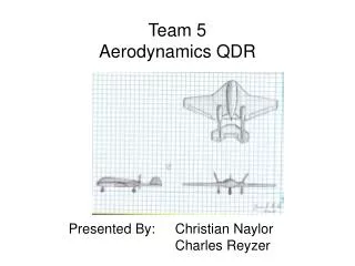
Team 5Aerodynamics QDR 2 Presented By: Christian Naylor Charles Reyzer
Outline • Aerodynamic Model • Trimability Considerations • Stability Considerations AAE 451 – Team 5
Mathematical Model – Lift CL vs α Lift vs. α Lift (lbs) CL α (deg) α (deg) AAE 451 – Team 5
Mathematical Model – Drag Drag Polar Drag Polar Drag (Lift) CD Lift (lbs) CL AAE 451 – Team 5
Mathematical Model – L/D • L/Dmax=13.21 • Loiter at α=.71°,4.46° • Loiter at 0.866*L/Dmax1 L/D vs. α L/D α (deg) 1 Raymer, D.P., Aircraft Design: A Conceptual Approach, Virginia, 1999, pp 27 AAE 451 – Team 5
Trim Diagram • Negative CMα for stability • Find CM0 • Find CMα Intro to Aeronautics: A Design Perspective, Steven A. Brandt et al AAE 451 – Team 5
Find CM0 CMac = Pitching Moment Coefficient about Wing AC (0.05) εo = Downwash at zero AOA (0) ito = Tail angle of incidence (0) AAE 451 – Team 5
Determine CMα CLα= Change in wing CL vs AOA (0.075 /deg) CLαt=Change in tail CL vs AOA (0.066 /deg) Xcg =Normalized center of gravity (0.89) Xac =Normalized center of gravity (1.00) Cmac = 0.717 ft VH = “Volume” of horizontal tail (0.11 cubic ft) dε/dα=Change in Downwash vs AOA (.7153) AAE 451 – Team 5
Trim Diagram Trim Point: 3.18 degrees AAE 451 – Team 5
Future Work • Class 2 Sizing of Control Surfaces • Adjust tail angle of incidence • Add elevator deflections to trim diagram • Ensure that the aircraft is stable in all directions • Verification of CM0 AAE 451 – Team 5